


DEEP CUTS
For deeper cuts, make several progressively
deeper cuts by starting with the highest step on
the depth turret, and after each cut, rotate the
depth turret to progressively lower steps as
desired, until the final depth (lowest step or flat)
is reached. Steps progress by 1/8” increments.
To be certain that your depth settings are as
desired, you may want to make test cuts in
scrap material before beginning work.
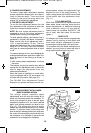
FINE ADJUSTMENT
The RA1166 plunge base is equipped with a
fine adjustment system that allows you to
micro adjust the plunge depth of the router bit
for superior routing accuracy.
Each complete revolution of the fine
adjustment stop adjusts the plunging depth by
1/32”, and each of the four indicator marks on
the knob represents 1/128”. One of the four
tick marks is larger than the other to indicate a
complete revolution. A reference indicator line
is built in to the depth rod.
To use the fine adjustment knob, once the
depth rod and turret have been set, check the
final depth setting and fine-adjust as follows:
To micro-increase the plunge depth, raise the
fine adjustment stop by turning it counter-
clockwise by the desired amount.
To micro-reduce the plunge depth, lower the
fine adjustment stop by turning it clockwise by
the desired amount.
2
1
0
IN
50
40
30
20
10
0
MM
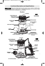
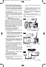
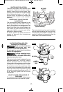
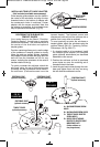
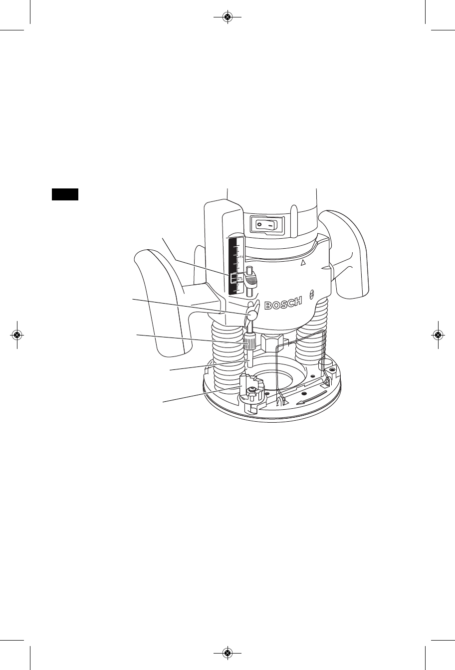
FIG. 13
DEPTH INDICATOR
KNOB
DEPTH
INDICATOR
DEPTH ROD
DEPTH STOP
TURRET
DEPTH ROD FINE
ADJUSMENT KNOB
-14-
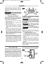
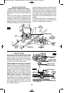
DEPTH ROD AND TURRET
The depth rod and the depth stop turret are
used to control cutting depth as follows;
1. With the bit installed, gently lower the motor
until the tip of the router bit just contacts the
level surface the router is sitting on. This is
the “zero” position, from which further depth
adjustments can be accurately made.
2. To set a desired depth of cut, rotate depth
stop turret until the lowest step is aligned
with the depth rod. Loosen depth indicator
knob and lower the depth rod until it
contacts the lowest step of the turret. Slide
the depth indicator until the red line indicates
zero on the depth scale, indicating the point
at which the bit just contacts the work
(Fig. 13).
3. To set a desired cutting depth, slide the
depth rod up until the red depth indicator line
attains the desired cutting depth, and secure
the rod in position by firmly tightening the
depth indicator knob.
4. The desired depth of cut may now be
achieved by plunging the router until the
depth rod contacts the selected stop on the
turret.
BM 2610018532 01-12:BM 2610018532 01-12.qxp 1/23/12 9:21 AM Page 14