


Chicago Pneumatic Compressors
62 305 258 65
01/2008
Page 11
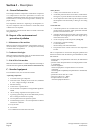
Section 4 - Operation
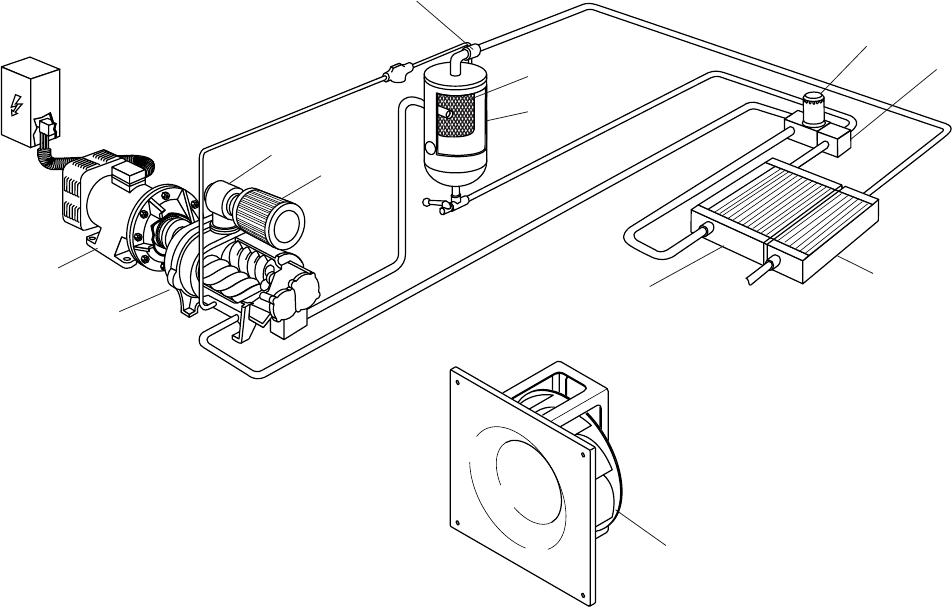
A - Air and oil circuits
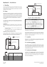
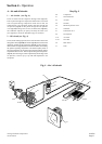
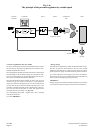
1 - Air circuits (see Fig. 4)
The air is sucked into the compressor through a filter (rep. 23).
This air passes through the compression element where it is mixed
with oil injected during compression. Inside the oil tank, the
compressed air is pre-deoiled by shocks, then flows through the
oil separator (rep 49). It then passes through the mini pressure
valve (rep 34) forming a check valve, the aftercooler (rep 51A),
the condensate separator (in option), and lastly the outlet valve
(not supplied) to which the distribution pipe is connected.
2 - Oil circuit (see Fig. 4)
The oil, under discharge pressure, flows from the bottom of the tank
through the cooler (rep. 51H), the oil filter (rep. 26) which retains solid
impurities, and then into the compressor (rep. 20). At each cold start,
the thermostat valve (rep. 47) short circuits the oil radiator, thus enabling
the optimum operating temperature to be attained quickly. When it
leaves the compressor, the oil returns to the tank. Part of the oil remains
suspended in the air as mist. This mist passes through the oil separator.
(rep. 49). The remaining oil, which is separated by the last stage of the
oil separator, is drawn up by a dip tube and dispatched to the
compressor.
Key fig. 4
20 Compressor
21 Suction element
23 Air filter
26 Oil filter
34 Minimum pressure valve
41 Ventilator
47 Thermostat valve
49 Oil separator
51 A Air cooler
51 H Oil cooler
56 Main motor
57 Tank
Fig. 4 - Air / oil circuit
20
56
41
34
23
57
51A
51H
49
26
47
21