


Chicago Pneumatic Compressors
62 305 258 65
01/2008
Page 6
Section 1 - Description
A - General Information
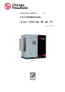
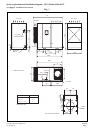
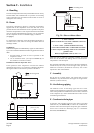
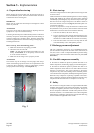
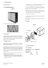
The Chicago Pneumatic Compressors CP model air compressor
is a compressed air unit and is presented as an entire unit
completely assembled and tested. It is driven by an electric motor
and enclosed in a sound proof cowling which is necessary for
proper cooling.
The compression element is a single-stage, oil-refrigerated, ro-
tary screw compressor. The oil is stored in a vertical tank, which
is fitted with an oil separator.
The compression element and the motor are fixed to the frame
using silent blocks.
B - Respect of the environment and
prevention of pollution
1 - Maintenance of the machine
Make sure that the used components of the machine (waste oil,
oil and air filters, oil separators, etc...) are disposed of according
to national and local regulations.
2 - Condensate bleed pipe
Make sure that the condensates (water, oil) are drained and treated
according to national and local regulations.
3 - End of life of the machine
Make sure that the machine as a whole is disposed of according to
national and local regulations ( See F Section 7 and J Section 8 ).
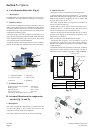
C - Standard equipment
In its standard version, the covered unit includes:
- Operating components:
1. A twinned screw-type compressor.
2. An electric motor: 3600 rpm, short-circuit rotor, 230/460V
or 575V voltage according to the model.
3. Star delta starting.
4. A direct drive or gearbox drive .
5. Air and oil tank in compliance with applicable legislation
ASME
6. "All or nothing" regulation for the aspiration vent.
7. A greasing system using the circuit's differential pressure,
thus avoiding the need for an oil pump.
8. An oil separator based oil separation system.
9. A heat discharge system : oil and compressed air radiator
with forced ventilation.
10. A dry air filter.
11. An oil filter.
12. A command and control electronic board.
- Safety devices:
1. A safety valve mounted on the oil reservoir.
2. An thermal protection device for the motor, situated in the
starting box, to protect the motor from excessive overload.
3. An air temperature sensor that stops the compressor when
the temperature rises abnormally or during an oil cooling
defect.
- Control devices:
1. A minimum pressure valve located at the oil tank outlet,
just beyond the oil separator, which guarantees minimum
pressure in the lubrication circuit.
2. Automatic draining allowing the unit to be exposed to the
atmosphere when stopping to thus ensure empty start up
which relieves the motor,
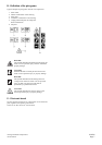
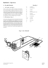
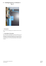
3. An oil level gauge on the front panel ( see fig. 19).
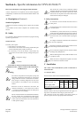
4. An electronic controller including:
– a control keyboard,
– the main safety and control indications.
5. The pressure sensor ensures control over the compressed
air flow.
The CP compressed air unit has been designed, produced and
tested in accordance with the following recommendations, codes
and standards :
- machine safety : European Directive 98/37/CE, 91/368/CEE and
93/68/CEE.
- pressure vessels: European Directive for simple pressure vessels
n° 87/404/CEE.
- electrical equipment :
• electrical equipment : European Directive Low tension
73/23/CEE.
• electromagnetic compatibility European Directive: 89/336/CEE,
92/31/CEE.
- performance levels: ISO 1217 : 1996.
- noise level : ISO 2157 + 3db(A)
- European Directive 97/23/EC
" Pressure Equipment Directive ".