


Chicago Pneumatic Compressors
62 305 258 65
01/2008
Page 16
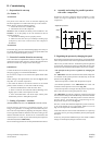
The inverter has a load circuit of thermally limited
capacitors. Therefore, it is important to allow minimum
5 minutes between two successive power-ons. If this
instruction is not respected, the switch and the resistor
of the load circuit may be damaged.
2 - Safety instructions
No connection work is allowed when the inverter is
under power.
No measurement work is allowed on the inverter when
it is under power.
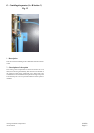
To undertake any work on the inverter, it is necessary
to disconnect the equipment from the mains. Wait for
the internal ventilation to stop and the indicators to be
turned off. Then, wait 5 minutes before opening the
cover.
No voltage or insulation verification test is allowed on
the inverter components.
Disconnect the cables from the motor and the inverter
before taking measurements on them.
Do not touch the integrated circuits, the electrostatic
discharges may damage them.
Before connecting the inverter, make sure that its cover
is properly closed.
Make sure that no compensation capacitor of cosine
phi is connected to the motor cable.
C - Installation
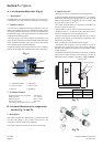
The "CPVS" must be installed away from a transformer or
autotransformer.
(see Section 2 and 3).
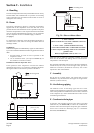
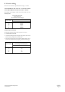
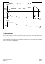
The fuses for the section switch are defined as follows
Main Voltage 460 Volt / 3 / 60 Hz
Nominal current (A) 69 81 100 126
Power supply cable AWG4 AWG3 AWG1 AWG0
Fuse protection (Type RK5) 80 100 125 150
ATTENTION
Motors and drives can only be guaranteed where the supply vol-
tage does not exceed the rated voltage by more than 10%.
The connection of the power supply to the section switch (so
present) requires the use of properly insulated terminals.
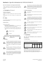
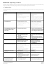
Section 6 - Specific information for CPVS 40-50-60-75
Refer also to the chapters concerning the standard machine.
"CPVS" compressors are compliant with the Electromagnetic
compatibility in industrial environments Standards 50081-2 and
50082-2
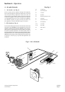
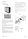
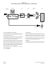
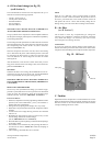
A - Description (cf Section 1)
Standard equipment
A electronic frequency adjusting device replaces the star-delta
starter.
A fuse holder section switch completes CP standard's safety
devices.
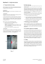
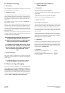
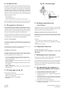
B - Safety
For your safety, please respect the instructions carrying the warning
symbols as given below:
SAFETY RULES
The safety rules require:
• The presence of an earth socket
• The existence of a manual switch cutting-off the three pha-
ses that should be placed visibly near the CP
• It is necessary to cut out the electric current before any
intervention on the machine (except drainage under pres-
sure).
= Dangerous voltage
= Attention
ELECTRICAL INSTALLATIONS MUST ONLY BE
CARRIED OUT BY A SPECIALISED AND COMPETENT
TECHNICIANS
1 - Warning
The internal components and the plates (except the
electrically insulated I/O terminals) are at the mains
voltage when the inverter is connected to the mains.
This voltage is extremely dangerous and can cause
severe injuries or even death in case of involuntary
contact.
When the inverter is connected to the mains, the
connection terminals U, V, W of the motor as well as
+/- connectors of the braking resistors are under power
even if the motor is not running.
The I/O control terminals are insulated from the mains,
the relay outputs can nevertheless be under power
even if the inverter is disconnected. This also applies
to other I/O control terminals even if the X4 switch is
in OFF position (Stop).
1
2
3
4
1
2
3
4
5
6
7
8
40 50 60 75