


Chicago Pneumatic Compressors
62 305 258 65
01/2008
Page 17
D - Commissioning
1 - Preparation for start-up
(See Section 3).
ATTENTION
The power circuit will have to be cut off when adjusting the
electrical equipment or if inadvertent start-up is to be avoided.
Before start-up, check the following points:
1 - Ensure that the unit has a suitable earth,
2 - Check the oil level in the compressor,
NOTE: the tank was filled in the factory with a suitable oil. See
Section 8 - A for the quality of oil to be used and for the oil
renewal conditions.
3 - Check that the drainage valve is properly closed.
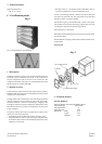
4 - Make sure that the conveyor assembly's blocking lugs
(compressor) have been removed from the compressor
silentblocks.
ATTENTION
The oil filler plug, the valve and the drainage plugs have always to
be closed during operation and must never be opened before the
system has reached atmospheric pressure.
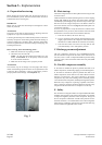
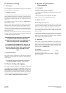
2 - Control of rotation direction on start up
This control must be implemented when the machine is put into
operation for the first time, after any work has been carried out on
the motor and after any changes to the mains supply.
IMPORTANT :
• Check the direction of rotation (as per the arrow shown on the
sump) by jogging over with the START button.
If it is incorrect, swap over two of the motor's phase cables under
the drive.
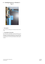
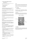
When rotating in the right direction, the oil level (fig. 19) must
drop after 4 to 5 seconds of operation.
• Also check the direction of rotation of the fan for air-cooled
plants (counter-clockwise, as seen from inside the casing).
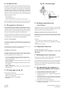
1 - Press the START button so that the motor starts.
2 - Allow to rotate for several seconds with the discharge valve
slightly open to observe the compressor at load.
3 - Press the STOP button. The motor stops and the plant
automatically returns to atmospheric pressure.
3 - Setting of pressure - machine
(Refer E Section 1 refer also to the AIRLOGIC controller manual)
The unit is factory pre-set for a given delivery pressure. As an
energy saving measure, it is strongly advised to reduce the pres-
sure to the exact requirement by adjusting the "Set point 1"setting.
The stop pressure"Indirect shutdown"used when running at less
than the minimum flow-rate - must be set to 7.25 PSI above that
of the "Set point 1". In this way, the current used by the compressor
is minimised (seenotice AIRLOGIC).
Do not set the stop pressure at a level beyond the machine's max P.
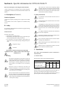
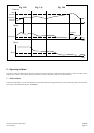
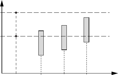
4 - Assembly and settings for parallel operation
with other compressors
Pressure for the CPVS compressor must be adjusted at a value
within the range of adjustment values for the rest of the
compressors..
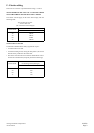
CPVS C1 C2 C3
Various
compressors
Adjustments pressure
Stop P
Set
point 1
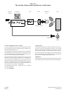
5 - Regulating the pressure by changing the speed
This method of regulating the pressure allows precise adjustment
of the compressor's flow-rate at the compressed air demand valve:
The accuracy is of the order of 1.45 PSI when pressure regulation
is achieved by changing the speed, provided that the flow-rate
lies between the maximum and minimum rates for the machine.
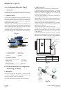
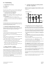
• The principle of the pressure regulation by changing the
speed
The AIRLOGIC controller controls the motor and the compressor
as a function of the system pressure as measured by an internal
pressure sensor (fig. 14a).
- If the mains pressure is weaker than the pressure set point
(user-defined parameter in the AIRLOGIC) the motor will
accelerate and the pressure will increase (fig. 14b)
- If the mains pressure is stronger than the pressure set point, the
motor will slow down causing the pressure to drop.
The AIRLOGIC provides the compressor control functions and
also controls the whole pressure feedback loop. It therefore includes
a device to compare the indicated pressure with that from the
pressure sensor, associated with a compensating device,
Proportional integral control PI (fig. 14c).
The drive, a result of the latest developments in power electronics,
is one of the smallest in size on the market, thanks to its use of
high cut-out frequencies with IGBT transistors.
At the same time, the motor control method known as "open loop
vector flux control " provides good stability for the system against
disruption.
In this way, the pressure feedback loop is more stable to sudden
changes in consumption (changes in the flow-rate).