


1-25
Cisco 8500 Series Wireless Controller Installation Guide
Chapter 1 Cisco 8500 Series Wireless Controller Installation Guide
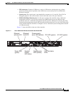
Rear Panel
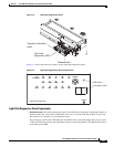
• USB connectors: Connect a USB device, such as a USB mouse or keyboard to any of these
connectors. During normal operation, these USB slots are not used by the Cisco 8500 Series
Wireless Controller.
• Console port: This console port is not intended for customer use. It is used by Cisco TAC for
debugging purposes. Do not discard the console cable that comes with your controller.
• IMM 10/100 Mbps Ethernet port: Use this port to manage the controller, using a dedicated
management network. If you use this connector, the IMM cannot be accessed directly from
production network. A dedicated management network provides additional security by physically
separating the management network traffic from the production network. You can use the immconfig
script provided with the controller to configure it to use a dedicated systems management network
or a shared network.
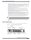
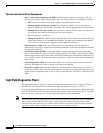
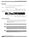
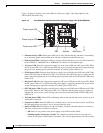
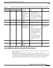
Figure 1-7 shows the LEDs on the rear of the controller.
Figure 1-7 Cisco 8500 Series Wireless Controller Rear Panel LEDs
282301
AC
DC
AC
DC
Ethernet
activity LED
Ethernet
link LED
Power LED
(green)
System-
locator
LED (blue)
System-error
LED (amber)
AC LED (green)DC LED (green)
Power-supply
error LED (amber)
10G link status
LEDs