


1-45
Cisco 8500 Series Wireless Controller Installation Guide
Chapter 1 Cisco 8500 Series Wireless Controller Installation Guide
Using the Startup Wizard
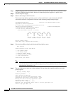
Step 6 Enter the IP address, netmask, default router IP address, optional VLAN identifier (a valid VLAN
identifier or 0 for an untagged VLAN), and the port number for the management interface.
Note The VLAN identifier should be set to match the switch interface configuration.
Management Interface IP Address: 192.168.1.10
Management Interface Netmask: 255.255.0.0
Management Interface Default Router: 192.168.1.1
Management Interface VLAN Identifier (0 = untagged): 192
Management Interface Port Num [1 to 2]: 1
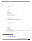
Step 7 Enter the IP address of the default DHCP server that will supply IP addresses to clients, the controller’s
management interface.
Management Interface DHCP Server IP Address: 192.168.1.1
Note The management interface is the default interface for in-band management of the controller and
connectivity to enterprise such as AAA servers.
Step 8 Enter the IP address of the controller’s virtual interface, which will be used by all controller Layer 3
security and mobility managers. You should enter a fictitious, unassigned IP
address, such as 1.1.1.1.
Virtual Gateway IP Address: 1.1.1.1
Note The virtual interface is used to support mobility management, DHCP relay, and embedded Layer
3 security such as guest web authentication and VPN termination. All controllers within a
mobility group must be configured with the same virtual interface IP address.
Step 9 If desired, enter the name of the mobility group/RF group to which you want the controller to belong.
Mobility/RF Group Name: amb
Note Although the name that you enter here is assigned to both the mobility group and the RF group,
these groups are not identical. Both groups define clusters of controllers, but they have different
purposes. All of the controllers in an RF group are usually also in the same mobility group and
vice versa. However, a mobility group facilitates scalable, system-wide mobility and controller
redundancy while an RF group facilitates scalable, system-wide dynamic RF management.
Step 10 Enter the network name, or service set identifier (SSID). The initial SSID enables basic functionality of
the controller and allows access points that have joined the controller to enable their radios.
Network Name (SSID): amb
Step 11 Enter yes to enable DHCP proxy or no to disable DHCP proxy.
Configure DHCP Bridging Mode [yes][NO]:yes
Step 12 Enter yes to allow clients to assign their own IP address or no to make clients request an IP address from
a DHCP server.
Allow Static IP Addresses [YES][no]:
Step 13 To configure a RADIUS server now, enter yes and then enter the IP address, communication port, and
secret key of the RADIUS server. Otherwise, enter no.