1-26
Cisco 8500 Series Wireless Controller Installation Guide
Chapter 1 Cisco 8500 Series Wireless Controller Installation Guide
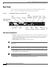
Rear Panel
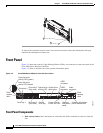
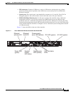
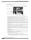
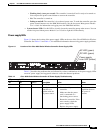
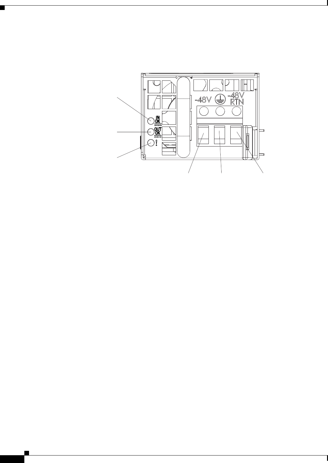
Figure 1-8 shows a detailed view of the LEDs on a DC power supply. This image applies to the
AIR-CT85DC-K9 model only.
Figure 1-8 Cisco 8500 Series Wireless Controller DC Power Supply LEDs (AIR-CT85DC-K9)
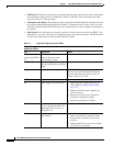
• Ethernet activity LEDs: When these LEDs are lit, they indicate that the controller is transmitting
to or receiving signals from the Ethernet LAN that is connected to the Ethernet port.
• Ethernet link LEDs: When these LEDs are lit, they indicate that there is an active link connection
on the 10BASE-T, 100BASE-TX, or 1000BASE-TX interface for the Ethernet port.
• AC power LED: Each hot-swap power supply has an AC power LED and a DC power LED. When
the AC power LED is lit, it indicates that sufficient power is coming into the power supply through
the power cord. During typical operation, both the AC and DC power LEDs are lit.
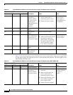
• IN OK power LED: Each hot-swap DC power supply has an IN OK power LED and an OUT OK
power LED. When the IN OK power LED is lit, it indicates that sufficient power is coming into the
power supply through the power cord. During typical operation, both the IN OK and OUT OK power
LEDs are lit.
• DC power LED: Each hot-swap power supply has a DC power LED and an AC power LED. When
the DC power LED is lit, it indicates that the power supply is supplying adequate DC power to the
system. During typical operation, both the AC and DC power LEDs are lit.
• OUT OK power LED: Each hot-swap DC power supply has an IN OK power LED and an OUT OK
power LED. When the OUT OK power LED is lit, it indicates that the power supply is supplying
adequate DC power to the system. During typical operation, both the IN OK and OUT OK power
LEDs are lit.
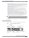
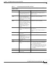
• 10 G link status LEDs: These LEDs individually indicate the transmit and receive activity of each
10
Gb SFP+ transceiver.
• System-error LED: When this LED is lit, it indicates that a system error has occurred. An LED on
the light path diagnostics panel is also lit to help isolate the error.
• Power-on LED: When this LED is lit and not flashing, it indicates that the controller is turned on.
The states of the power-on LED are as follows:
–
Off: Power is not present, or the power supply or the LED itself has failed.
–
Flashing rapidly (4 times per second): The controller is turned off and is not ready to be
turned on. The power-control button is disabled. This will last approximately 20 to 40 seconds.
-48V return
Ground
-48V
Power input LED
Power output LED
Power error LED
255133


