


1-38
Cisco 8500 Series Wireless Controller Installation Guide
Chapter 1 Cisco 8500 Series Wireless Controller Installation Guide
Replacing a Hot-Swap -48 VDC Power Supply
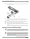
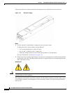
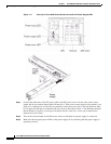
Figure 1-11 Close Up of Cisco 8500 Series Wireless Controller DC Power Supply LEDs
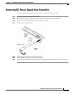
Step 4 Connect the other ends of the DC power cable to the DC power source. Cut the wires to the correct
length, but do not cut them shorter than 150 mm (6 in.). If the power source requires ring terminals, you
must use a crimping tool to install the ring terminals to the power cord wires. The ring terminals must
be UL approved and must accommodate the wires that are described in Note
1. The minimum nominal
thread diameter of a pillar or stud type of terminal must be 4 mm; for a screw type of terminal the
diameter must be 5.0 mm.
Step 5 Turn on the circuit breaker for the DC power source to which the new power supply is connected.
Step 6 Make sure that the green power LEDs on the power supply are lit, indicating that the power supply is
operating correctly.