


b. LOWVOLTAGE- Althoughthemotoris de-
signedfor operationon the voltage and fre-
quency specified on the motor nameplate,
normal loads will be handled safely on voltages
not more than 10% above or below the name-
plate voltage. Heavy loads, however, require
that voltage at motor terminals equals the
voltage specified on nameplate.
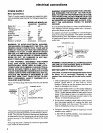
5. Most motor troubles may be traced to loose or
incorrect connections, overload, reduced input
voltage (such as small size wire in the supply
circuit) or to overly long supply circuit wire.
Always check the connections, the load and the
supply circuit whenever motor fails to perform
satisfactorily. Check wire size and length with
the Wire Size Chart below.
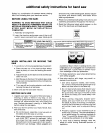
WIRE SIZES
The use of any extension cord wil! cause some loss
of power. To keep this to a minimum and to prevent
overheating and motor burn-out, use the table below
to determine the minimum wire size (A.W.G) exten-
sion cord, Use only 3-wire extension cords which
have 3-prong grounding type plugs and 3-pole
receptacles which accepts the tools plug.
CAUTION: For circuits that are farther away from
electrical service box, the wire size must be increased
proportionately in order to deliver ample voltage to
the saw motor.
|
Length of the _ 120 Volts Wire Sizes Required
Conductor 1 (American Wire Gage Number)
0 - 25 Ft. I 14
26 - 50 Ft. 12
51 - 100 Ft. _ 8
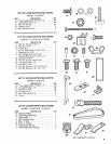
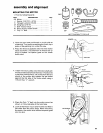
unpacking and checking contents
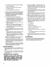
TOOLS NEEDED
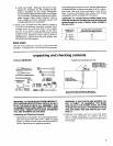
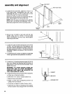
COMBINATION SQUARE MUST BE TRUE
MEDIUM SCREWDRIVER
#2 PHILLIPS SCREWDRIVER
:::::::::::::::: ::::::: -,
COMBINATION
SQUARE
1/8" HEX "L" WRENCH
5/32" HEX "L" WRENCH
3iB" WRENCH
T/16" WRENCH
9/16" WRENCH
3/8" SOCKET _ _
7/16" SOCKET
9/16" SOCKET
_ SOCKET WRENCH
I
I
1
I
I
I
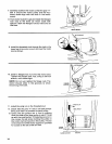
DRAW LIGHT I
LINE ON BOARD
ALONG THIS EDGE __
L_
/
SHOULD BE NO GAP OR OVERLAP HERE WHEN
SQUARE IS FLIPPED OVER IN DOTTED POSITION
STRAIGHT EDGE OF
BOARD 3/4-1NCH THICK
THIS EDGE MUST BE
PEFCTLY STRAIGHT
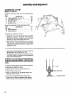
WARNING: TO AVOID INJURY FROM UNEXPECT-
ED SfARTING OR ELECTRICAL SHOCK, DO NOT
PLUG THE SAW IN UNTIL ALL ASSEMBLY AND
ALIGNMENT STEPS ARE COMPLETE. THE POWER
CORD MUST REMAIN UNPLUGGED WHENEVER
YOU ARE WORKING ON THE SAW.
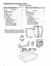
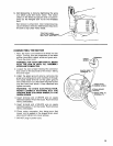
Unpacking and Checking Contents
1. Separate all "loose parts" from packaging mater-
ials and check each item with "Table of Loose
Parts" to make sure all items are accounted for,
before discarding any packing material.
,
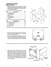
WARNING: IF ANY PARTS ARE MISSING, DO
NOT ATTEMPT TO ASSEMBLE THE BAND
SAW, PLUG IN THE POWER CORD, OR TURN
THE SWITCH ON UNTIL THE MISSING PARTS
ARE OBTAINED AND ARE INSTALLED COR-
RECTLY.
Remove front table and front cover first while
saw is being unpacked. To remove the front
cover, pull the cover at the neck and underside of
th roat area.