


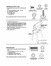
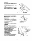
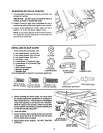
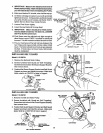
ADJUSTING RiP SCALE POINTER
1. Turn Elevation Handwheel clockwise untilblade isup
as high as itwill go.
IMPORTANT: BLADE must be SQUARE (90°) to
TABLE, in order to ALIGN Rip Scale.
2. Position Fence on right side of sawblade so that it
touches the sides of the teeth, tighten Lock Handle.
3. Loosen screw holding the Pointer, adjust so that it
pointsto "0" on the Rip Scale, tighten screw.
NOTE: If you cannot adjust Pointer so that it points to
"0", loosen the screws holding the Front Guide Bar
and move the Guide Bar.
LOCK HANDLE
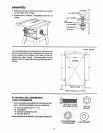
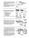
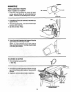
INSTALLING BLADE GUARD
1. From among the loose parts, find:
*2 Hex Head Screws, 1/4-20 x 5/8
*3 Hex Head Screws, 5/16-18 x 5!8
*2 Hex Head Screws, 5/16-18 x 1
*2 Hex Nuts, 1/4-20
*2 Lockwashers, 1/4 Extemal Type
*2 Lockwashers, 5/16 ExternalType
"1 Thumbscrew
1 Blade Guard Support
1 Spreader Support
1 Spreader Rod
@
1/4-20
HEX NUT
Q
_161N.
EXTERNAL
LOCKWASHER
Items marked with an astedk (*) are shown actual size.
1/4-20 X 5/8 IN.
HEX HD. SCREW 5/16-18 X 5/8 IN.
HEX HD. SCREW
5/16-18 X 1 IN.
, HEX HD. SCREW
©
1/4 IN.
EXTERNAL
LOCKWASH ER
BLADE GUARD
SUPPPORT
THUMBSCREW
SPREADER ROD
SPREADER SUPPORT
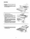
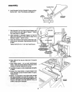
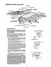
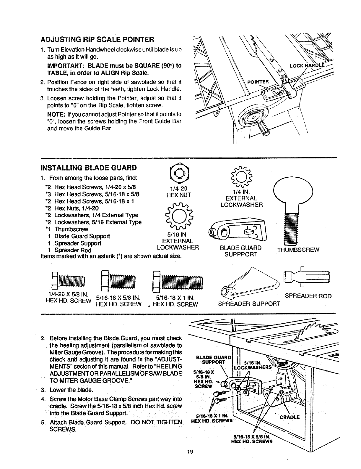
2. Before installing the Blade Guard, you must check
the heeling adjustment (parallelism of sawblade to
Miter Gauge Groove). The procedure for making this
check and adjusting it are found in the "ADJUST-
MENTS" secion of this manual. Refer to "HEELING
ADJUSTMENTOR PARALLELISM OFSAW BLADE
TO MITER GAUGE GROOVE."
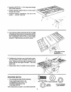
3. Lower the blade.
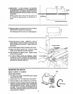
4. Screw the Motor Base Clamp Screws part way into
cradle. Screw the 5/16-18 x 5/8 inch Hex Hd. screw
into the Blade Guard Support.
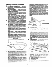
5. Attach Blade Guard Support. DO NOT TIGHTEN
SCREWS.
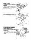
BLADE (
SUPPORT
\
5/16-18 X
5/8 IN.
HEX HD.
SCREW
5/16.18X1 IN. ]
HEX HD. SCREWS
5116-18 X 5/8 IN
HEX HD. SCREWS
19