


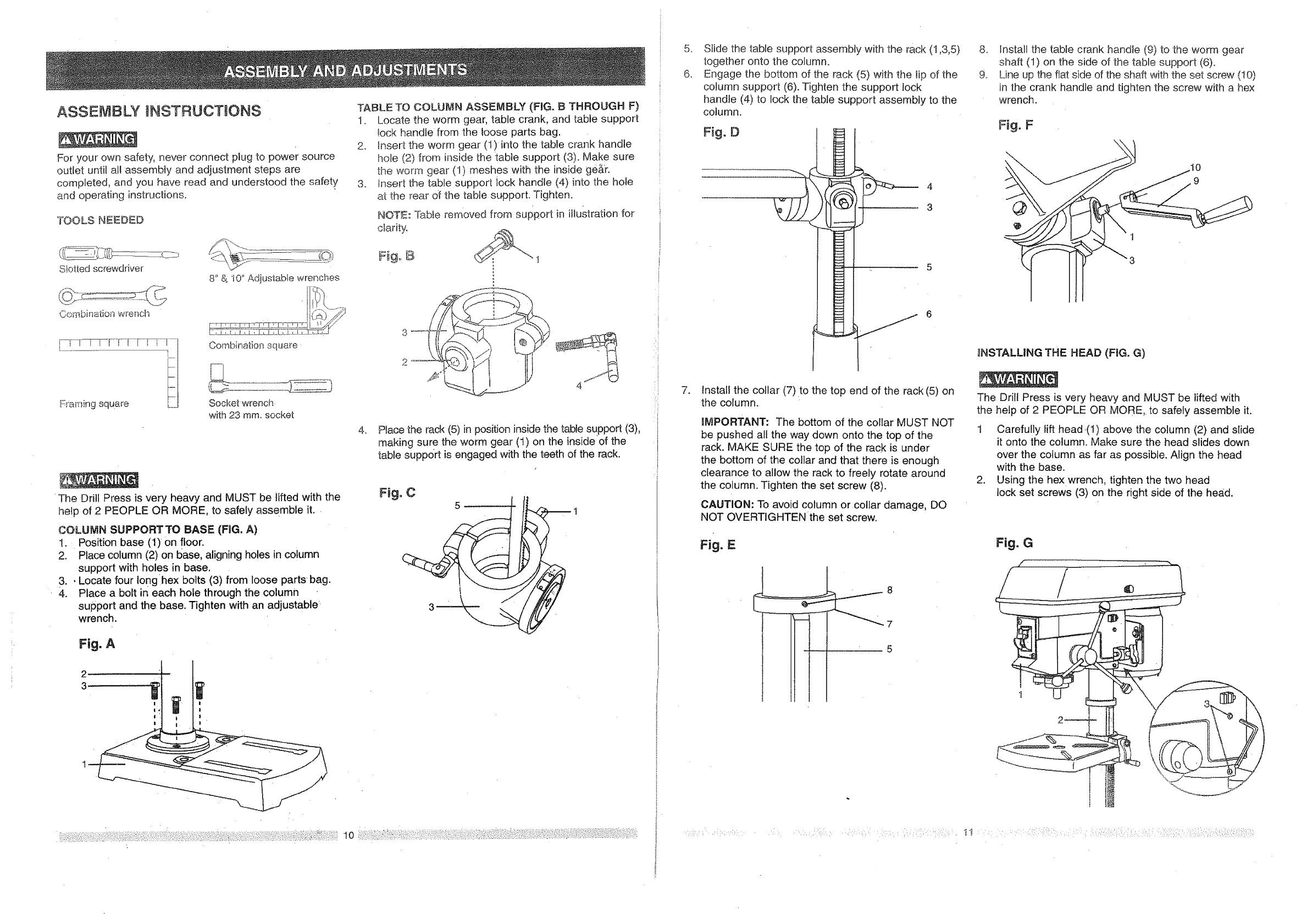
ASSEMBLY tNSTRUCTMONS
For your own safety, never connect plug to power source
outlet until af! assembly and adjustment steps are
completed, and you have read and understood the safety
and operating instructions.
TOOLS NEEDED
c_ot[edscrewdriver
Combination wrench
8" & 10" Adjustabfe wrenches
Combination square.
Socket wrench-
with 23 ram. socket
The Drill Press is very heavy and MUST be lifted with the
help of 2 PEOPLE OR MORE, to safely assemble it.
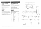
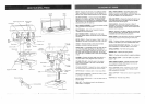
COLUMN SUPPORT TO BASE (FIG. A)
!. Position base (1)on floor.
2. Place column (2) on 10ase,aligning holes in column
support with holes in base,
3. , Locate four Ionghex bolts (3) from loose parts bag.
4. Place a bolt in each hole through the column
support and the. base. Tighten with an adjustable'
wrench.
Fig. A
TABLE TO COLUMN ASSEMBLY (FIG. B THROUGH F)
1. Locate the worm gear, table crank, and table support
lock handle from the loose parts bag.
2. Insert the worm gear (1)into the table crank handle
hole (2) from inside the table support (3). Make sure
the worm gear (!) meshes with the inside ge&r.
3. Insert the table support Jock handle (4) into the hole
at the _ear of the table support. Tighten.
NOTE: Table removed from support in illustration for
clarity.
Fig_ B
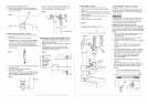
4_
Place the rack (5) in position inside the table support (3),
making sure the worm gear (1) on the inside of the
table support is engaged with the teeth of the rack.
Fig. C
5 ' 1
2
3
|
i
[
J
/i _
:1
,
6_
,
Slide the table support assembly with the rack (1,3,5)
together onto the column.
Engage the bottom of the rack (5) with the tip of the
column support (6). Tighten the support lock
handle (4) to lock the table support assembly to the
column.
Fig. D
4
3
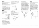
Install the collar (7)to the top end of the rack (5) on
the column.
IMPORTANT: The bottom of the collar MUST NOT
be pushed all the way down onto the top of the
rack. MAKE SURE the top of the rack is under
the bottom of the collar and that there is enough
clearance to allow the rack to freely rotate around
the column. Tighten the set screw (8).
CAUTION: To avoid column or collar damage, DO
NOT OVERTIGHTENthe set screw.
Fig. E
..........._...- 8
"--""-_"'-_"J-"--7
5
r,:_;,_ : i::':;:k ; :: :-;J i::: : d : q : o:::: i://: {:v _i>::'ij:i,_
8. Install the table crank handle (9) to the worm gear
shaft (1) on the side of the table support (6).
9. Line up the flat side of the shaft with the set screw (!0)
in the crank handle and tighten the screw with a hex
wrench.
Fig. F
• IO
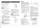
_NSTALLING THE HEAD (FIG. G)
The Drill Press is very heavy and MUST be lifted with
the help of 2 PEOPLE OR MORE,. to safely assemble it.
1 Carefully lift head,(1) above the column (2) and slide
it onto the column. Make sure the head slides down
over the column as far as possible. Align the head
with the base.
2. Using the hex wrench, tighten the two head
lock set screws (3) on the right side of the he,_d.
Fig. G
/-
I! :: :::::: :::: :] :::'::