


To prevent personal injury, always disconnect the plug from
the power source when making any adjustments.
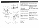
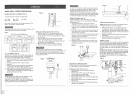
SQUARING TABLE TO HEAD (FIG. O, P)
NOTE: The table and support has a predrilled hole with a
locking pin inserted for locking thetable to a predetermined
0° horizontal position. It must be loosened to change the
angle of the table.
I. Insert a 1/4", or larger diameter, precision ground
steel rod (1), approximately 3" long, into the chuck (2).
Tighten the chuck jaws.
2. Raise table to working height and lock.
3. Using the combination square (3), place one edge
flat on the table, and align the other edge vertically
beside the rod (1).
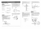
4. (Figure Q) If an adjustment is necessary, TIGHTEN
the nut (4) on the locking pin clockwise to RELEASE
it from the table support.
5. Loosen the large hex head bevel locking bolt (5).
To prevent injury, be sure to hold the table & table arm
assembly, so it wil! not swivel or tilt.
6. Align the square to the rod by rotating the table until
the square and rod are in line.
7. Retighten the large hex bolt (5).
Fig. O
2
1
I I I I I I _' ...
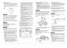
BEVEL SCALE (FIG. P)
NOTE: The bevel scale has been included to measure
approximate bevel angles. If precision is necessary,
a square or other measuring toot should be used to
position the table. To use the bevel scale (6):
I. TIGHTEN the nut (4) on the locking pin clockwise to
RELEASE it from the table support.
2. Loosen the large hex head bevel locking bolt (5).
3. Tilt the table, aligning the desired angle measurement
to the zero line opposite the scale (6).
4. Tighten the bevel locking bolt. (5).
,
.
To return the table to its original position, loosen the
bevel locking bolt (5). Realign the bevel scale (6) to
the 0° position.
Return nut (4) on locking pin to the OUTSIDE END
OF THREADS. Gently tap locking pin until it is seated
in the hole. Finger tighten nut (4).
NOTE: The table has been removed from the
illustration for clarity.
Fig. P
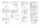
SPINDLE/QUILL (FIG. Q)
Rotate the feed handles counterclockwise to lower spindle
to its lowest position. Hand support the spindle securely
and move it back and forth around its axis.
If there is too much play, do the following:
!. Loosen lock nut (1)..
2. Turn the screw (2) clockwise to eliminate the play, but
without obstructing the upward movement of the
spindle. (A little play in the spindle is normal.)
3_ Tighten the lock nut (1),
Fig. Q
2
i,i
E
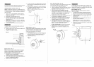
QU_LL RETURN SPRING (FIG, R)
The quill return spring may need adjustment if the tension
causes the quill to return too rapidly or too slowly.
t. Lower the table for additional clearance.
2, Place a screwdriver in the lower front notch (1) of the
spring cap (2). Hold it in place while loosening and
removing only the outer jam nut (3).
3. With the screwdriver still engaged in the notch,
loosen the inner nut (4) just until the notch (5)
disengages from the boss (6) on the drill press head.
CAUTION: DO NOT REMOVE THIS INNER NUT,
because the spring will forcibly unwind,
4. Carefully turn the spring cap (2) counterclockwise with
the Screwdriver, engaging the next notch.
5. Lower the quill to the lowest position by rotating the
feed handle in a counterclockwise direction while
holding the spring cap (2) in position,
6. If the quill moves up and down as easily as you
desire, tighten the standard nut (4) with the adjustable
wrench. If too loose, repeat steps 2 through 5 to
tighten. If too tight, reverse steps 4 and 5.
=
To avoid injury from an accidental start, ALWAYS make
sure the switch is in the "OFF" position, the switch key is
removed, and the plug is not connected to the power source
outlet before making belt adjustments.
BELTTENSiON (FroG.S)
Make sure pulleys are aligned properly as shown in
Figure O on page 13.
1. To unlock the belt tension, loosen the belt tension
lock knobs (1) on both sides of the drill press head.
2. Move the motor (2) toward the front of the drill press
to loosen the belt.
3. Position the belt on the correct pulley steps for the
desired speed.
4. Pull the motor away from the drill press head until
the belt is properly tensioned.
DO NOT OVERTIGHTEN and restrict quill movement.
,
NOTE: Belt tension is correct if the belt deflects
approximately 1/2 inch when pressed at the center.
Tighten the belt tension lock knobs (1) on both sides
of the drill press head.
Replace the jam nut (3) and tighten against the
standard nut (4) to prevent the standard nut from
reversing.
Fig. S
..... , ,,..... ,,,,, =_
6 1
1
3 4
L
y