


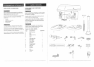
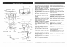
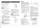
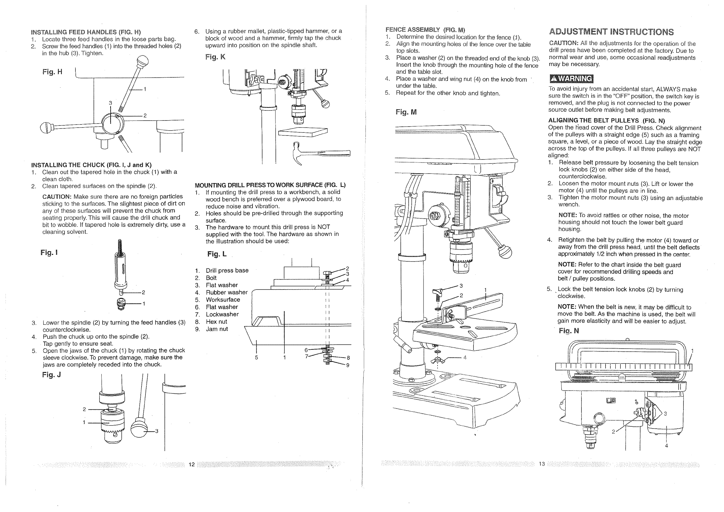
_NSTALMNG FEED HANDLES (FIG. H)
1. Locate three feed handles in the loose parts bag.
2. Screw the feed handles (1) into the threaded holes (2)
in the hub (3). Tighten.
INSTALLING THE CHUCK (FIG. t, J and K)
t. Clean out the tapered hote in the chuck (1) with a
clean cloth.
2. Clean tapered surfaces on the spindle (2).
CAUTION: Make sure there are no foreign particles
sticking to the surfaces. The slightest piece of dirt on
any of these surfaces will prevent the chuck from
seating properly. This will cause the drill chuck and
bit to wobble. If tapered hole is extremely dirty, use a
cleaning solvent.
Fig.I
2
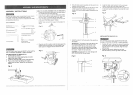
3. Lower the spindle (2) by turning the feed handles (3)
counterclockwise.
4. Push the chuck up onto the spindle (2).
Tap gently to ensure seat.
5. Open the jaws of the chuck (t) by rotating the chuck
sleeve clockwise. To prevent damage, make sure the
jaws are completely receded into the chuck.
Fig. J
2 --
ti
3
,
Using a rubber maltet, plastic-tipped hammer, or a
block of wood and a hammer, firmly tap the chuck
upward into position on the spindle shaft.
Fig, K
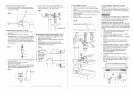
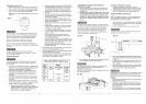
MOUNTING DRILL PRESSTO WORK SURFACE (FIG. L)
1. If mounting the drill press to a workbench, a solid
wood bench is preferred over a plywood board, to
reduce noise and vibration.
2. Holes should be pre-drilled through the supporting
surface.
3. The hardware to mount this drill press is NOT
supplied with the tool. The hardware as shown in
the illustration should be used:
Fig. L
1. Drill press base
2. Boft
I
3. Flat washer i
4. Rubber washer
5. Worksurface
6. Flat washer |
7. Lockwasher !
Hex nut __
8.9. Jam nut _\
\
"1
5
I
Ii
It
i i .......................
tt
6 _
E
E
FENCE ASSEMBLY (F_G°M}
t. Determine the desired location for the fence (.1).
2. Aiign the mounting holes of the fence over the table
top slots.
3. Place a washer (2) on the threaded end of the knob (3).
Insert the knob through the mounting hole of the fence
and the table slot.
4. Place a washer and wing nut (4) on the knob from '
under the table.
5. Repeat for the other knob and tighten.
Fig. M
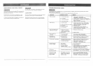
ADJ UST 'V ENT INSTRUCTIONS
CAUTION: All the adjustments for the operation of the
drill press have been completed at the factory. Due to
normal wear and use, some occasional readjustments
may be necessary.
To avoid injury from an accidental start, ALWAYS make
sure the switch is in the "OFF" position, the switch key is
removed, and the plug is not connected to the power
source outlet before making belt adjustments.
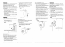
ALIGNING THE BELT PULLEYS ,(FIG. N)
Open the t_ead cover of the Drill Press. Check alignment
of the pulleys with a straight edge (5) such as a framing
square, a level, or a piece of wood. Lay the straight edge
across the top of the pulleys. If all three pulleys are NOT
aligned:
1. Release belt pressure by loosening the belt tension
lock knobs (2)on either side of the head,
counterc!ockwise.
2. Loosen the motor mount nuts (3). Lift or lower the
motor (4) until the pulleys are in line.
3. Tighten the motor mount nuts (3) t_sing an adjustable
wrench.
4,
,
NOTE: To avoid rattles or other noise, the motor
housing should not touch the lower belt guard
housing.
Retighten the belt by pulling the motor (4) toward or
away from the drill press head, until the belt deflects
approximately t/2 inch when pressed in the center.
NOTE: Refer to the chart inside the bett guard
cover for recommended drilling speeds and
belt / pulley positions.
. Lock the belt tension lock knobs (2) by turning
clockwise.
NOTE: When the belt is new, it may be difficult to
move the belt. As the machine is used, the belt will
gain more elasticity and will be easier to adjust.
Fig. N
¢h
,,_ ........ >s
........... i 3 :::::::::::::::::::::::::::::::::::::::::::::::::::::::::::::::::::