


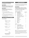
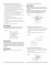

ASSEMBLESTAND(FIG.A)
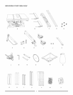
1 Unpackallpartsandgroupbytypeandsize Refer
totheparts!istforcorrectquantities
2 Attachonelonguppersupport(S)totopofleg(V)
usingonebolt(1)andnut(2)
NOTE:Donottightenboltsuntilstandisproperly
aligned(seestep#9beforetightening)
3 Attachotherendof Io%uppersupporttotopof
anotherlegusingoneboltandnuL
4 Attachonelongbottomsupport(U)tocenterofeach
legusingbolt(1)andnut(2) Thiscompletesthe
frontframesection
5 Assemblerearframesectioninexactlythesame
manner
6 Joinfrontandrearframeassembliesusingtwoshort
uppersupports(R)andtwoshortbottomsupports
(T),boltsandnuts
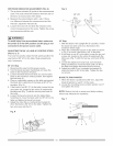
7 Insertlargehexheadbolt(3)intorubberfoot(4)and
insertintobottomof leg Fastenwithwasher(5)and
nut(6) Repeatforeachleg
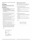
8 Attachthefencestoragehooks(16)totheframeas
shownwithbolt(7)andnut(8)
9 Placestandonlevelsurfaceandadjustsoalllegs
arecontactingthefloorandareatsimilaranglesto
thefloorAligningthedetentsinthelegtothemating
partofthestandthentightenal!bolts
NOTE:Standshouldnotrockafteral!boltsare
tightened
Fig.A
J
16
T
1 V
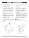
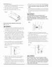
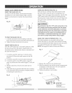
ASSEMBLE TABLE SAW TO STAND (FIG. B)
1 Place protective cardboard or old blanket on floor to
protect the saw table surface
2 Place the saw up side down on the protective
materia! (see Fig B)
3 Place dust chute on the saw base so the tapered
chute is facing up
4 Position the stand up side down on the saw base
NOTE: Make sure front of stand and front of saw are
facing the same direction
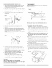
5 Line up the four holes in saw base, dust chute and
stand
6 Fasten saw to stand using four bolts (9), washers
(10) and nuts (11)
NOTE: Place washer on each bolt before inserting
into saw base and through the supporL Nut must be
immediately against the bracket (see Fig A)
7 Tighten all four nuts
NOTE: Do not over tighten nuts holding saw to tand
This may damage the saw base After the hardware
is finger-tight, turn two full times
8 Carefully set the saw in its upright position on a
clean level surface
[,& WARNING]
if the stand will not be used, do not operate the table
saw on the fmoor. This is a very dangerous position.
Fig. B
10