


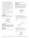
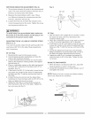
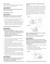

RiPFENCEiNDiCATORADJUSTMENT(FIG.Q)
1_Theripfenceindicator(6)pointstothemeasurement
scale.Thescaleshowsthedistancefromthesideof
thefencetonearestsideoftheblade.
2_Measuretheactualdistancewitha rule.if there
isadifferencebetweenthemeasurementandthe
indicator, adjust the indicator (6)_
3_ Loosen the screw (7) and slide the indicator to the
correct measurement on the scale. Tighten the screw
and remeasure with the rule.
IA WARNINGn
To avoid injury from an accidental start, make sure
the switch is in the OFF position end the plug is not
connected to the power source outtet.
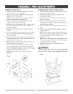
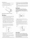
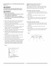
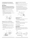
ADJUSTING THE 90° (0°) AND 45 ° POSiTiVE STOPS
(FIG. R, S, T}
Your saw has positive stops that will quickly position the
saw blade at 90 ° (0°) to the taNe. Make adjustments
only if necessary.
O0° (0°) Stop
1. Disconnect the saw from the power source.
2. Turn the blade elevation handwheel and raise the
blade to the maximum elevation.
3. Loosen the blade bevel lock knob (1) and move the
blade to the maximum vertical position, then tighten
the lock knob (1).
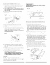
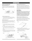
4. Place a combination square on the table and against
the blade (2) to determine if the blade is 90° (0°) to
the table. (Fig. S)
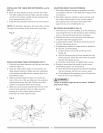
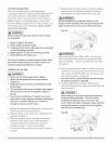
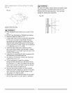
5. If the blade is not 90° (0°) to the table, loosen the two
set screws (4), located on the collar (5) underneath
the table saw (Fig. T) with the hex key and back off
the collar.
6. Loosen the bevel lock knob, turn the blade tilting
handwheel to move the blade until it is 90° (0°) to the
table and tighten the bevel lock knob.
7. Adjust the collar (5) so it contacts the bracket (3)
when the blade is 90° (0°) to the table. Tighten the
two set screws (4) (Fig.T).
Fig. R
o
Fig. S
9o°(0o)
45 °
45° Stop
1. With the blade in the upright 90° (0°) position, loosen
the bevel lock knob and move the blade to the
maximum bevel angle.
2. Place the combination square on the table as shown
in Fig. S to check if the blade is 45° to the table.
3. If the blade is not 45 ° to the table, loosen the two set
screws (4), located on the collar (5) underneath the
table saw, (Fig. T) with the hex key, and back off the
collar.
4. Loosen the bJade bevel lock knob, turn the blade
tilting handwheel to move the blade until it is 45° to
the table and tighten the blade beve! lock knob.
5. Adjust the collar (5) so it contacts the bracket (3)
when the blade is 45° to the table. Tighten the two
set screws.
BLADE TILTING POINTER
1. When the blade is positioned at 90° (0°), adjust the
blade tilt pointer to read 0° on the scale.
2. Loosen the mounting screw, position pointer over 0°
and tighten the screw.
NOTE: Make a trial cut on scrap wood before making
critical cuts. Measure for exactness.
Fig. T
4
5
3
3 4 5
15