


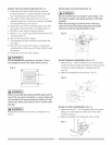
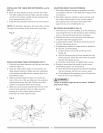
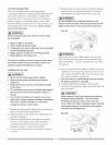
BLADEGUARDASSEMBLY(FIG.K,L, M)
1. Setthebladetomaximumheightandthetilttozero
degreesonthebevelscalewiththehandwheels.
Lockthebladebevellockknob.
2. Placethespringwasher(2),flatwasher(3),external
toothlockwasher(4)ontothebladeguardmounting
bolt(1)(Fig.K).
3. Insertboltandwasherassemblythroughsplitter
bracket(5).
Fig.K
BladeGuard/-
Splitter
5
J 1
\
11
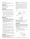
4. Place the oval washer (6) on the pivot rod (7)
(Fig. L).
5. Install the blade guard splitter & bracket assembly
into the rear of the saw table. Thread the bolt (1) into
the internally threaded pivot rod until snug.
NOTE: The blade guard and splitter is removed from
the illustration for clarity.
Fig. L
J
7 6
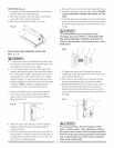
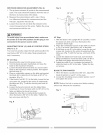
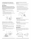
6. Lift blade guard arm (8) up and using a straight
edge, align the blade guard splitter (9) with the saw
blade (10).
7. Shift the splitter bracket assembly to right or left until
parafle! alignment to the blade is achieved.
8. When the splitter is properly aligned with the saw
blade, tighten the bolt securely.
NOTE: The splitter bracket must always be
correctly aligned so the cut workpiece will pass
on either side without binding or twisting.
CAUTION
See Fig. K fiat washer (11} must be under
knob (12}. NOTE: Be sure to tighten knob very tight
and periodically check tightness.
[_ DANGER]
Improper splitter alignment can cause "kickback"
and serious injury.
Fig. M
8 10
Anti-Kickback Pa_I / //
9
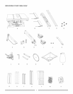
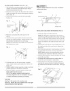
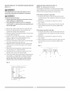
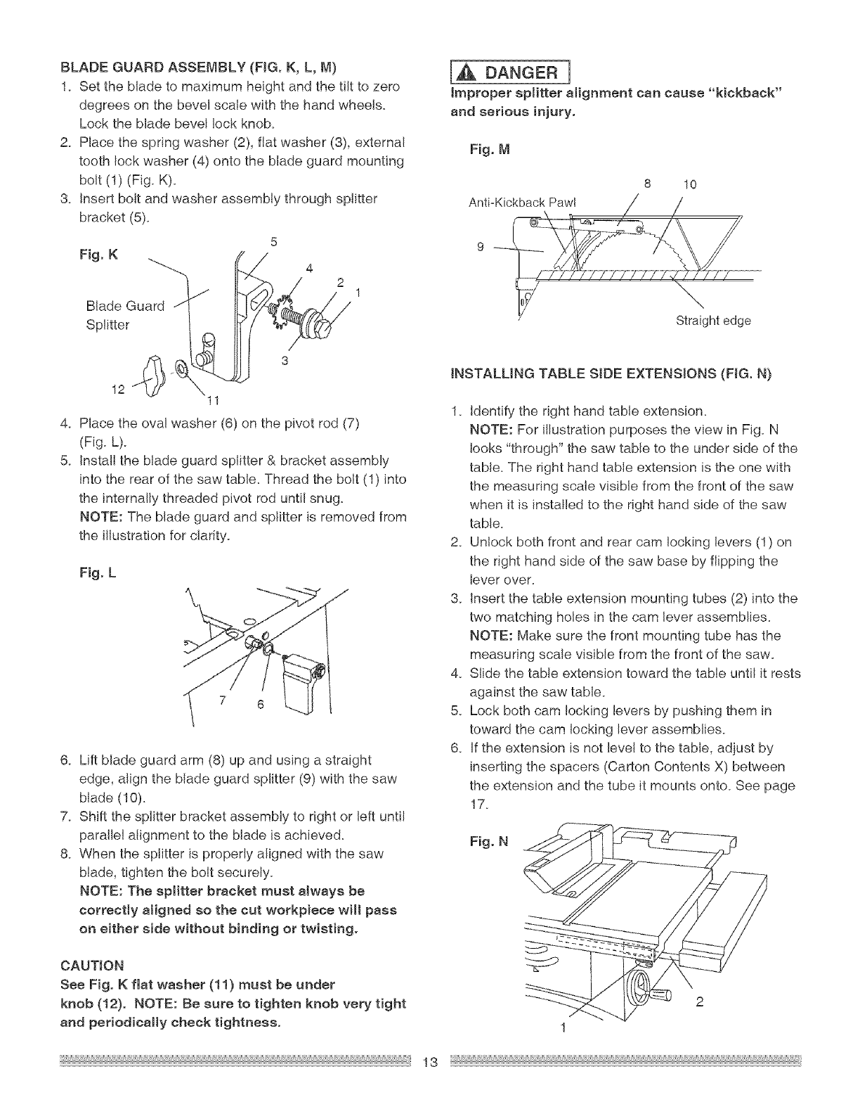
INSTALLING TABLE SIDE EXTENS!ONS (FIG. N)
1. Identify the right hand table extension.
NOTE: For illustration purposes the view in Fig. N
looks "through" the saw table to the under side of the
table. The right hand table extension is the one with
the measuring scale visible from the front of the saw
when it is installed to the right hand side of the saw
table.
2. Unlock both front and rear cam locking levers (1) on
the right hand side of the saw base by flipping the
lever over.
3. insert the table extension mounting tubes (2) into the
two matching holes in the cam lever assemblies.
NOTE: Make sure the front mounting tube has the
measuring scale visible from the front of the saw.
4. Slide the table extension toward the table until it rests
against the saw table.
5. Lock both cam locking levers by pushing them in
toward the cam locking lever assemblies.
6. If the extension is not level to the table, adjust by
inserting the spacers (Carton Contents X) between
the extension and the tube it mounts onto. See page
17.
Fig. N
2
1
13