


Page 9
Craftsman
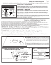
3. With router completely plunged and locked., center long drive nut and housing bushing assembly on #1 mainshaft. Secure
using two 11/16" wrenches.
6. With plunge lock disengaged, make sure plunging action operates smoothly, If not, loosen drive nut re-center and retighten.
fig 8
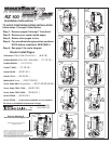
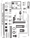
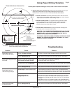
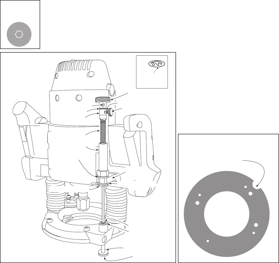
4. Select #12 green bushing ( Two #15 retainers ) #21 lead screw, #22 rapid collar, #23 O-ring, #24 thumb screw, #26 top drive,
#27 yellow set screw, #28 allen wrench, red grease. Using ( fig 8 ) place grease on threads of #21 lead screw, Place lead
screw down #1 mainshaft and thread into #20 long drive nut leaving one inch of lead screw threads exposed .
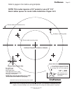
Alignment of #1 mainshaft and #21 screw hex is required ( fig 7 ). Tip: # 29 speed wrench can be used to speed threading.
#26 Top Drive
#24 Thumb Screw
#23 O-Ring
#15 One Retainer
#14 Steel 3/16"
Washer
#7 Brass Washer
fig 9
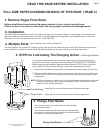
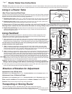
Locate raizer access point on original subbase.
Drill a 3/4" hole through subbase
Access hole Drill 3/4"
#15 retainer clip
install teeth up
#17 Housing Bushing
Washer
#27 Yellow Set Screw
© 2000-2005 Router Technologies
All Rights Reserved
U Shaped
Height Rod
Boss
5. Press #23 O-ring onto #24 thumb screw shaft. Thread thumb screw into #22 rapid collar. Place rapid collar onto #1 mainshaft
1/2" from top of mainshaft to top of rapid collar and tighten. Release plunge lock and slowly raise the router until lead screw
contacts the rapid collar. If the collar moves, reset to 1/2". Place one #15 retainer teeth up on top of #1 mainshaft, using #12
green bushing as installation tool, push retainer into contact with collar, repeat with second #15 retainer and push flush with first
retainer. Return # 12 green bushing to box. Place #26 top drive onto #1 mainshaft until it contacts retainer clip. Thread #27 yellow
set screw into #26 top drive using #28 allen wrench and tighten. Reinstall rubber dust boots.
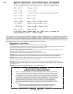
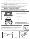
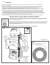
2. See pages 4,5,6 for further instruction, #30 dust cover insert and #31 dust cover, are table insert only. Drill a 1/2" hole
through insert plate at the Router Raizer access point and press #30 in from top until flush. # 31 sets in #30 and is
removed during adjustments with magnet on back edge of # 29 speed handle. These components keep dust from
entering the Router Raizer hex drive.
3. Periodic inspection and re-greasing of #21 lead screw is recommended.
Sub-base Plate or Router Table Insert Plate Installation
1. Use #46 locating pin to locate the Router Raizer access hole on the original subbase or router table. For detailed
instructions see page 4. Drill original subbase hole to 3/4" ( fig 9 ). Use the three optional router plate mounting
holes for router table applications.
fig 7
Top veiw of #21 lead
screw and #1 main-
shaft through center.
#1 Mainshaft
#15 Two Retainers
#22 Rapid Collar
#21 Lead Screw
#20 Long Drive Nut
#18 Drive Nut
Washer
#16 Housing Bushing