


Page 5
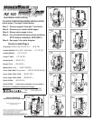
Preparing and Drilling Router Table Top Method #2 (A ) and ( B )
METHOD #2 ( A ) Black Rubber spacer
METHOD #2 ( B ) Routers Original Sub Base
METHOD #2 ( A ) Black Rubber spacer
METHOD #2 ( B ) Routers Original Sub Base
© 2000-2005 Router Technologies
All Rights Reserved
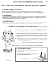
Installing #30 Dust Cover Insert and #31 Dust Cover
#31 Dust Cover
#30 Dust Cover Insert
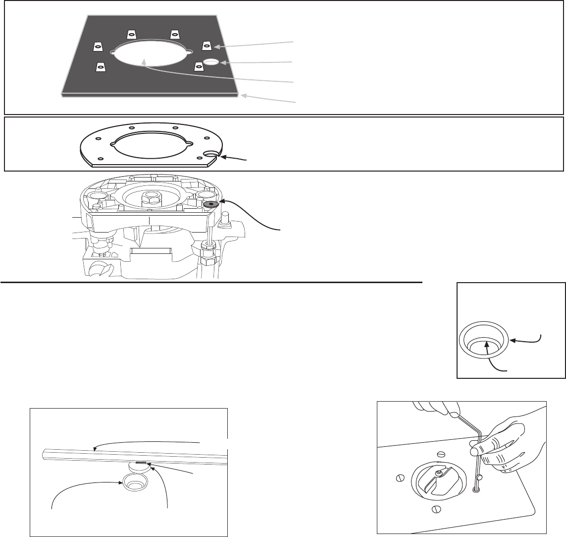
1. Using ( fig 7 ) select #30 dust cover insert ( 1/2" dia, X 3/16" tall, turned aluminum ring ) and #31 dust cover
( 3/8" dia. X 1/8 thick stamped steel plug ) From top of insert plate, press #30 cover insert into the
1/2" Router Raizer access hole until flush.
Tip: If cover insert fits loosely, secure with drop of Super Glue® or Krazy Glue®.
Top
Install #30 dust cover insert
Stop Ring Down
Stop Ring
3. Place #31 dust cover into #30 dust cover insert. Using ( fig’s 1 & 2 ) remove #30 dust cover with magnet on
back of #29 speed wrench. With dust cover on speed wrench, insert wrench to make adjustments. To reinstall
dust cover, place cover into insert and slide wrench away. Caution: Remove dust cover with speed wrench
before removing router from table or cleaning table with vacuum sweeper.
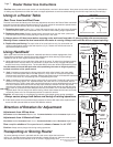
2. Mount router to insert plate and install into table
Mounting holes cut out either round or square
NOTE: All installations require a 1/2" diameter hole drilled through the top of your router table top or insert plate to
accept the #30 dust cover insert shown bottom of page.
Some table tops and steel insert plates do not allow cutting the pocket from the back side. An 8" X 8" black rubber spacer is provided to
cut out and place between the router and the table top or insert plate.
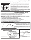
1. Place the rubber spacer onto base of your router with the pre-punched 3/4" hole centered on the #1 mainshaft head.
2. Use a utility knife or raiser blade to cut out the center hole and router mounting holes. Note: Mounting holes can be cut square and
rounding outside of spacer is optional. This method may require slightly longer mounting screws.
Pre stamped 3/4" hole placed over #1 mainshaft head
Center hole cut out to match router
8" X 8" black rubber spacer
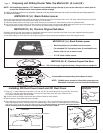
Preferred method for steel insert plates or installations where the router is secured to the plate using a pre designed clamping system.
This method may also be used in place of method #2 ( A )
1. Use #46 locating pin, then drill 3/4" hole through original sub base and secure subbase to router with original screws.
3/4" hole through original sub base, using forstner or spade bit
#1 mainshaft head protruding above base of router
NOTE: DeWalt router shown for illustration purposes only
Mainshaft head can protrude on most installations.
fig 1
#29 Speed Wrench
Magnet
Insert Plate
Install #30 dust cover insert
Stop Ring Down
#30 dust cover
insert
If metod #1 drilling pocket is not possible, a spacer must be placed between the router and table top providing space for
#1 mainshaft rotation.
fig 2