


Router Raizer Use Instructions
Page 7
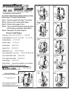
Using Handheld
Using in a Router Table
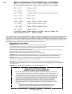
Caution: Always make sure router switch is in the off position, and tool is disconnected from power source when performing maintenance
or making any adjustments to either the router or height adjustments to avoid accidental starting of tool which may result in personal injury.
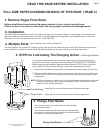
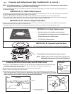
Dust Cover Insert and Dust Cover
The dust cover insert and dust cover allow easy adjustment access to the Router Raizer mainshaft
and restricts dust and debris infiltration during use. A small magnet is recessed into speed wrench
handle to remove and hold the dust cover during adjustments.
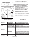
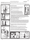
1. Removing dust cover: Using ( fig 1 ) place #29 speed wrench over #31 dust cover, lift speed-
wrench to remove dust cover. Leave dust cover on wrench while making height adjustments.
#31 Dust Cover
#30 Dust Cover Insert
fig 1
#29 Speed Wrench
Magnet
Insert Plate
fig 3
fig 2
2. Replacing dust cover: Position speed wrench with dust cover over the insert, press cover
into insert and swipe wrench away leaving the dust cover in the insert.
3. Always remove #31 dust cover before removing router and insert from table. Or cleaning table with vacuum sweeper
Warning: Never remove the dust cover while the router is running. Allways wait until the bit has stopped spinning.
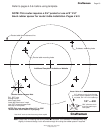
Direction of Rotation for Adjustment
One complete rotation of the speedwrench, raises or lowers the bit 1/16"
Caution: Always secure plunge lock during routing operations.
1. Height adjustments can be made from either end of the router. To adjust from the base, engage
#29 speed wrench into the head of #1 mainshaft. To adjust from the top, engage #29 speed
wrench into the top of #26 top drive. The knurled #26 top drive also allows adjustments by hand.
The #24 thumb screw and #22 rapid collar allow positioning the cutter to height. bypassing
multiple revolutions of the speed wrench
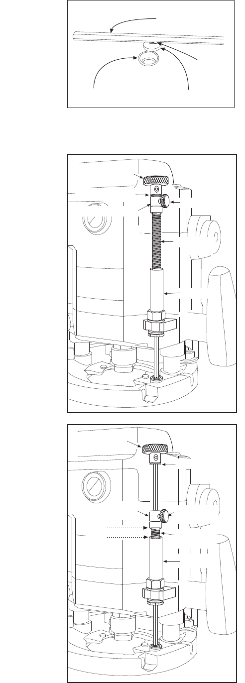
1. ( fig 2 ) Illustrates compressing the plunge router with rapid collar locked in the router table
position. Insert #29 speed wrench into #26 top drive, or lay router on its side and insert #29
speed wrench into bottom of #1 mainshaft. Rotating the speed wrench will thread #21 lead screw
in or out of the drive nut, compressing and un compressing the router.
4. Rapid collar positioning: The rapid collar is for hand held use only, for router table use
position collar against retainer clips and top drive ( fig 2 ). Secure with #24 thumb screw or
optional #25 black set screw.
When used hand-held the hex shaped #1 mainshaft provides a constant engagement of the
Router Raizer mechanism, allowing easy height adjustments while retaining original plunge
capabilities and all other original functions of the router.
1/2"
2. ( fig 3 ) Illustrates compressing the plunge router with the rapid collar. Thread #21 lead screw into
the drive nut leaving approx 1/2" exposed threads, the router will be un compressed. Secure
desired router bit in collet, stand router upright hand plunge to approx desired depth lock plunge
lock lever. Release #24 thumb screw and drop rapid collar into contact with #21 lead screw.
secure thumb screw and release plunge lock lever. Insert #29 speed wrench into #26 top drive,
or lay router on its side and insert #29 speed wrench into bottom of #1 mainshaft and adjust to
required depth. Re lock plunge lock before routing. When done release thumb screw and router
will quickly return to the un compressed position for easier bit removal.
4. If #24 thumb screw will not provide enough pressure to secure #22 rapid collar, replace thumb
screw with #25 optional black set screw and #28 allen wrench.
Caution: #22 rapid collar is not designed to maintain cutter height during routing operations.
Always secure plunge lock before and during all routing operations.
Adjustments from #26 top drive:
Clockwise rotation Decreases depth of cut. Counterclockwise rotation Increases depth of cut.
Adjustments from #1 Mainshaft Head :
Clockwise rotation Increases depth of cut. Counterclockwise rotation Decreases depth of cut.
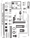
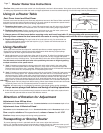
Transporting or Storing Router
#24 Thumb
Screw
#15 Retainers
To prevent damage to the #1 mainshaft and #21 lead screw, adjust the lead screw
leaving 1/2" threads exposed. Grasp router handles, release plunge lock, advance router up until
lead screw rapid collar and retainers are all in contact, engage plunge lock.
#21 Lead
Screw
Drive Nut
#22 Rapid
Collar
#26 Top Drive
#21 Lead
Screw
Drive Nut
#22 Rapid Collar
#26 Top Drive
#24 Thumb
Screw
#15 Retainers
Replace drive nut and #21 lead screw. Call 1-866-266-1293
© 2000-2005 Router Technologies
All Rights Reserved