


Page 4
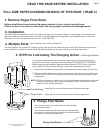
METHOD #1 ( Drilling 3/4" Pocket in Back of Insert Plate requires min 3/8" thick plate )
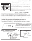
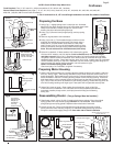
Using the #46 Locating Pin
Use this pin to simplify locating the Router Raizer access hole required through the original subbase or router table.
Using fig 1 support router upside down on bench and place locating pin into bottom of #1
mainshaft head. Secure subbase to router base gently tightening screws. Using a hammer
gently tap the subbase over the pin. Remove subbase and drill hole on center punch mark
using the Router Raizer template instructions.
Locating Hole in Original Subbase
Locating Hole in Router Table
If your router table is already drilled to mount the router, use above step using table or insert
plate in place of original subbase.
If your router table or insert plate have not been drilled use the provided paper template or
original subbase to first locate and drill the router mounting holes, then use #46 locating pin
to drill Router Raizer access hole.
Plunge
Post
fig 1
#1 Mainshaft
#1 Mainshaft
Head
Bottom
Router Base
# 46 Locating Pin
Original Subbase or Router Table
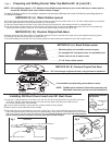
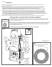
Preparing and Drilling Router Table Top
fig 2
fig 3
© 2000-2005 Router Technologies
All Rights Reserved
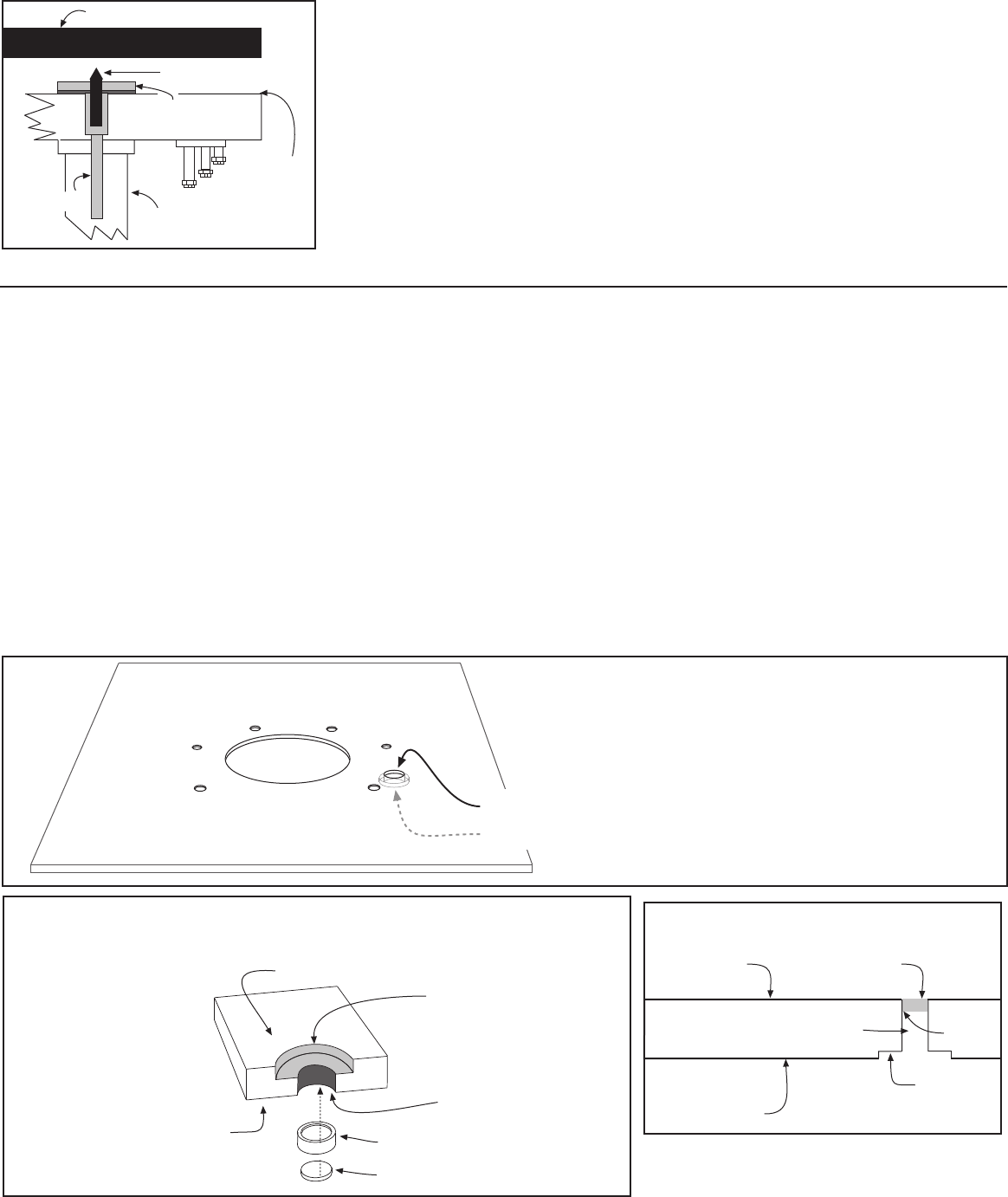
Side view of insert or table top
3/4" Pocket
3/32" Deep
1/2" Hole Through
Insert Plate or
Table Top
#30 Dust
Cover Insert
Top Side
Bottom Side
Super
Glue
1/2" DIAMETER HOLE
FROM TOP
3/4" DIAMETER
3/32" DEEP
POCKET FROM BOTTOM
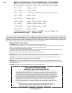
NOTE: For highest accuracy, the locating pins point should just project above the #1 mainshaft
head. Shorten the pin to desired length by securing pointed end of locating pin in jaws of cord-
less or electric drill. Grind but end of pin off and debur ground end.
Cool pin before removing from chuck jaws!
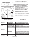
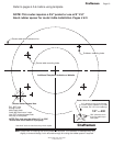
CUTAWAY ILLUSTRATION OF 3/4" POCKET
SHOWN FROM BOTTOM SIDE
BOTTOM SIDE OF INSERT PLATE
TOP SIDE OF INSERT PLATE
#30 Dust Cover Insert
#31 Dust Cover
1.
2.
1. Use the #46 locating pin to mark the back of the insert plate or table top.
2. Center 1/8" drill bit on locating pin center mark and drill completely through plate or top.
3. CAUTION 3/4" pocket must be drilled on the bottom side of plate or table top. (fig’s 2 & 3 )
From bottom side, center 3/4" forstner bit on 1/8" pilot hole and drill pocket no deeper than 3/32"
4. From top side, center 1/2" drill bit on 1/8" pilot hole and drill through into 3/4" pocket.
5. From top side, press #30 dust cover insert into 1/2" hole until flush with top surface. If insert is loose in 1/2" hole, place a
drop of super glue from bottom side around edge of the insert ring. ( fig’s 3 & 4 )
1. Determine if the head of the #1 mainshaft protrudes above the base of your router ( shown Fig 1 above )
A. If the head of the #1 mainshaft does not protrude above the base of your router, use #46 locating pin then drill a 1/2" hole
throught table top or insert plate and install #30 dust cover insert as shown at bottom of page 5
B. If the head of the #1 mainshaft protrudes above the base of your router clearance is required for the head of #1 mainshaft to
rotate freely. Select either method #1 or #2 ( page 4 and 5 ) and follow instructions for selected method.
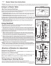
METHOD #1 Pocket ( requires min 3/8" plate )
This is the preferred method as it allows you to directly bolt the router
to the plate eliminating the black rubber spacer or original sub base
providing maximum collet height of your router when fully raised.
1/2" diameter hole drilled through the top of your router table
3/4" diameter pocket drilled from bottom of your router table