


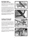
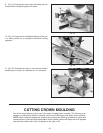


14
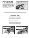
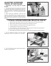
Fig. 28
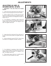
Fig. 29
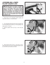
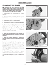
7. Loosen the two fence locking screws, one of which is
shown at (A) Fig. 28, and move the fence (B) all the way
to the rear position, as shown. Then tighten the two fence
locking screws (A).
8. Using a square, place one end of the square against
the blade and the other end against the table and check
to see if the fence is 90 degrees to the blade.
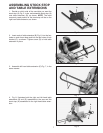
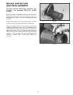
9. If an adjustment is necessary, loosen the two fence
locking screws (A) Fig. 28, and turn the two adjusting
screws, one of which is shown at (E) Fig. 29, until you are
sure fence is at 90 degrees to the blade when the fence
is all the way to the rear. Then tighten the two fence lock-
ing screws (A) Fig. 28.
10. These adjustments enable you to rapidly position the
fence in either the forward or rear position making sure
that the fence will be 90 degrees to the blade.
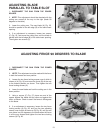
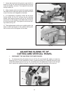
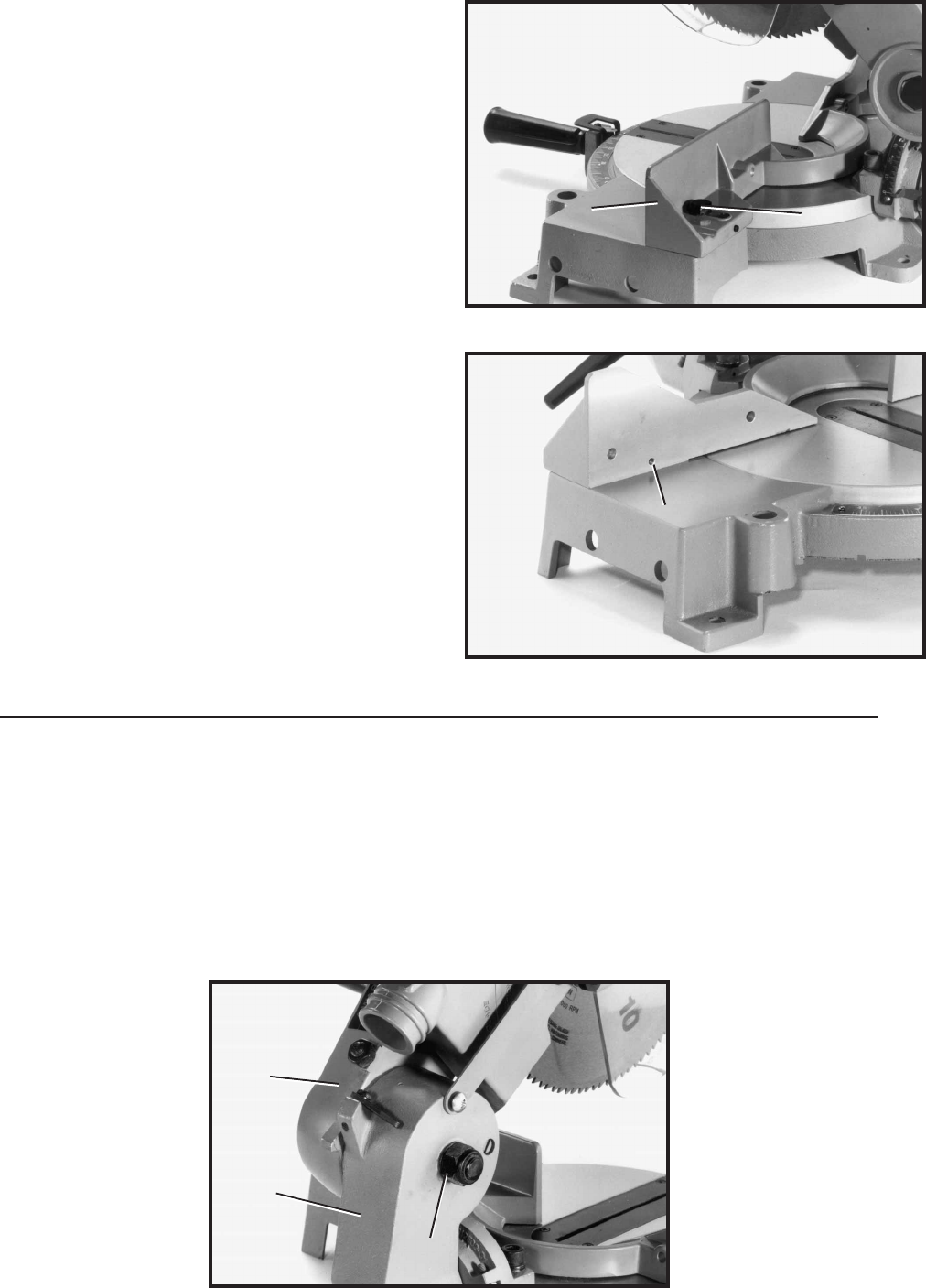
ADJUSTING SLIDING FIT OF
CUTTING ARM VERTICAL TRAVEL
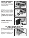
1. DISCONNECT THE SAW FROM THE POWER SOURCE.
2. To adjust the sliding fit between the arm (A) Fig. 30, and bracket (B), tighten or loosen the
adjusting nut (C). Correct adjustment is when a good snug sliding fit is obtained without any side
movement between the arm (A) Fig. 30, and bracket (B). This adjustment should not be too tight
that it restricts the sliding movement or too loose that it affects the accuracy of the saw cut.
Fig. 30
A
E
B
A
B
C