10
ADJUSTING RAIL STOP
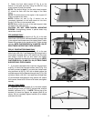
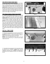
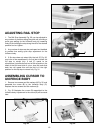
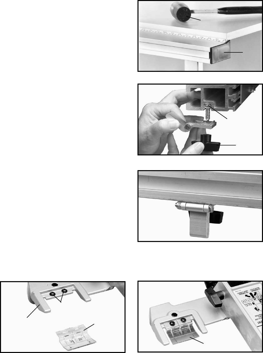
1. The Rail Stop Assembly Fig. 30, can be adjusted to
any number of positions along the guide rail providing a
quick stop setting for the Unifence body by loosening
knob (G) and sliding the stop along the rail to the desired
position and re- tighten.
2. Any number of stops can be purchased and installed
to provide time saving quick stop adjustment for the
Unifence body.
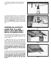
3. If flip stop does not retract fully the bolt (F) Fig. 30,
may have to be repositioned in the rail slot to allow the
flip stop to retract fully. If bolt (F) needs to be
repositioned, just slide the bolt out of the rail and turn the
head of the bolt one third of a turn (one flat) and slide
back into rail, repeat this until the bolt is in the right
position for the flip stop to retract fully. Fig. 31.
Fig. 29
Fig. 30
Fig. 31
ASSEMBLING CURSOR TO
UNIFENCE BODY
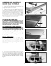
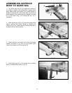
1. Remove two screws and flat washers (A) Fig. 32, and
assemble the cursor (B) to the Unifence body (C).
Replace the two screws and flat washers (A).
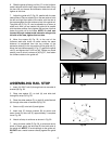
2. Fig. 33 illustrates the cursor (B) assembled to the
Unifence body. Adjustment to the cursor (B) will be made
later.
Fig. 32 Fig. 33
P
R
F
G
A
C
B
B


