


6
FOR DELTA TABLE SAWS ONLY
9. Fasten the table adapter plate (B) to the right side of
the saw table. Place a 7/16" lockwasher onto a 7/16-
20x1" hex head screw (D), insert screw through the table
adapter plate and thread screw into right side of saw
table. Repeat this process for the two remaining holes.
NOTE: Before tightening screws (D), use a straight edge
to make sure top of the adapter plate (B) is level with or
slightly below surface of the saw table. Also make sure
that the front edge of the adapter (B) does not stick out
past the front edge of the saw table.
FOR T
ABLE SAWS OTHER THAN DELTA
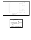
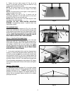
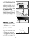
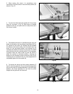
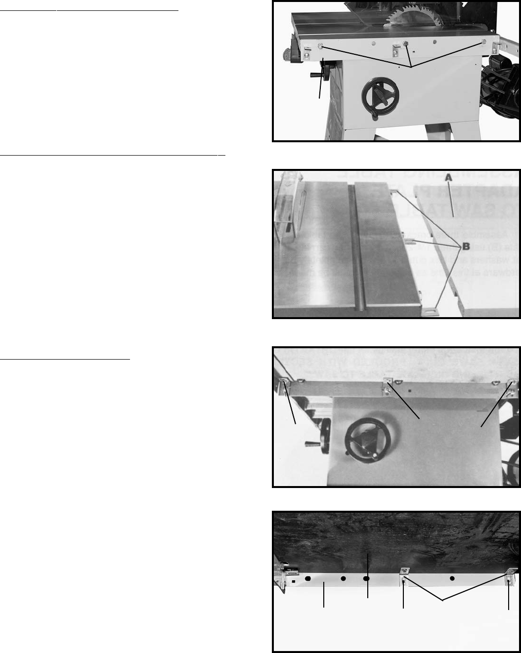
9. Assemble table adapter plate (B) Fig. 12, to the right
side of the saw table as shown using three 3/4 inch
screws, lockwashers and hex nuts (not supplied).
IMPORTANT: If the pre-drilled holes in adapter plate do
not line up with the holes in the saw table, new holes
must be drilled in adapter plate (B) and/or saw table.
NOTE: Do not drill any hole to fasten adapter plate (B)
Fig. 12, to the saw table that will be located less than
two inches from either end of the adapter plate. Before
tightening three screws (D) Fig. 12, place a straight edge
(E) on the saw table and make certain the top of adapter
plate is level with or slightly below the surface of the saw
table. Also, make certain front of adapter plate (B) Fig.
12, does not extend out past the front edge of the saw
table.
FOR ALL TABLE SAWS
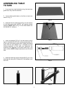
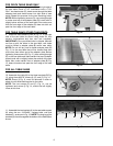
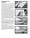
10. Assemble the table (A) to the three brackets (B) Fig.
13, using three #8x7/8" screws (I), (E), and (F), Fig. 14.
NOTE: Screw (I) Fig. 9, must be removed in order to
attach the left side table bracket to the table.
NOTE: The two screws (E) and (F), Fig. 14, can be
tightened and screw (I) Fig. 14, should be left slightly
loose at this time.
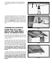
11. Assemble the two brackets (J) to the rear table support
(K) using the two 1/4-20x3/4" carriage bolts, nuts and
washers (L), as shown in Fig. 15. NOTE: The long leg of the
brackets (J) should be against the bottom of the table (M) as
shown.
Fig. 12
Fig. 13
Fig. 14
I
E
F
B
D
Fig. 15
J
K L
L
M