


12
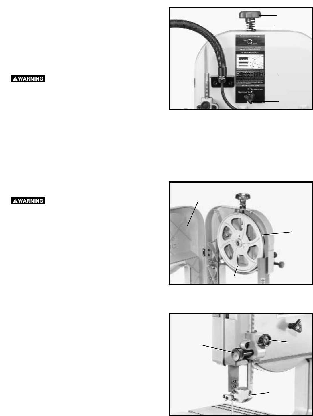
Fig. 19
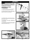
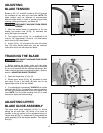
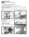
ADJUSTING
BLADE TENSION
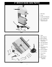
Blades of 1/8", 1/4", and 3/8" in width by 59-1/2" in length
are available for use with your band saw. NOTE: The
blade tension must be adjusted to accommodate
different blade widths in order to provide proper blade
tracking, cutting performance, and blade life.
DISCONNECT MACHINE FROM POWER
SOURCE.
1. After the desired blade is assembled to the two
wheels, turn tension knob (A) Fig. 19, clockwise until
spring (B) begins to compress.
2. Turn tension knob (A) Fig. 19, an additional 2-1/2
turns for 1/8" wide blades; 3 turns for 1/4" wide blades;
and 4 turns for 3/8" wide blades.
3. A chart (C) Fig. 19, is located at the rear of the band
saw. This chart shows blade size, and the minimum
radius that can be cut with each size blade.
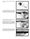
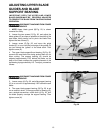
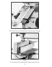
Fig. 20
TRACKING THE BLADE
DISCONNECT MACHINE FROM POWER
SOURCE.
1. Before tracking the blade, make sure the blade
guides and blade support bearings are clear of the blade
so as not to interfere with the tracking adjustment. Also
make sure that the blade is tensioned properly. (Refer to
section “ADJUSTING BLADE TENSION”).
2. Open the hinged door (C) Fig. 20.
3. Rotate upper wheel (A) Fig. 20, clockwise by hand
and check to see if the blade (B) rides true on the
approximate center of the two wheels.
4. If an adjustment is necessary, SLIGHTLY turn blade
tracking knob (D) Fig. 19, clockwise to move the blade to
the rear, and counterclockwise to move the blade to the
front. NOTE: Turn the blade tracking knob (D) in small
intervals to adjust the blade tracking.
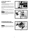
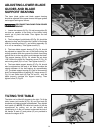
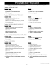
Fig. 21
ADJUSTING UPPER
BLADE GUIDE ASSEMBLY
The upper blade guide assembly (A) Fig. 21, should
always be no more than 1/8" above or as close as
possible to the top surface of the workpiece being cut.
Loosen knob (B) Fig. 21, rotate knob (C) and position the
guide assembly (A) to the desired position. Then tighten
knob (B).
A
B
A
B
C
D
C
B
A
C