


15
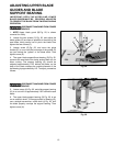
ADJUSTING THE TABLE
POSITIVE STOPS
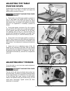
Positive stops are provided for the table at the 90 and 45
degree angle to the blade. To check and adjust the
positive stops, proceed as follows:
DISCONNECT MACHINE FROM POWER
SOURCE.
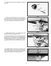
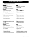
1. Tilt the table to the 90 degree position as shown in
Fig. 27, and tighten lock handle (A) Fig. 28. Place a
square (H) Fig. 27, on the table and against the blade
and check to see if the blade is 90 degrees to the table
surface. If an adjustment is necessary, proceed as
follows:
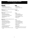
2. Tilt the table slightly as shown in Fig. 26, to expose
lock nut (E) Fig. 27. Loosen lock nut and return table to
the 90° position. With the lock handle (A) Fig. 28 loose,
turn adjusting screw (F) Fig. 27, using the wrench (G)
provided until the blade is 90 degrees to the table. Then
tighten lock nut (E) Fig. 27, and lock handle (A) Fig. 28.
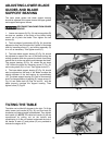
3. Tilt the table to the 45 degree position as shown in
Fig. 28. Place a square (H) on the table and against the
blade and check to see if the blade is 45 degrees to the
table surface. If an adjustment is necessary, proceed as
follows:
4. Loosen lock nut on adjustment screw (J) Fig. 28,
located on the underside of the table. With lock handle
(A) Fig. 28 loose, turn adjustment screw (J) using wrench
(G) provided until the blade is 45 degrees to the table.
Then tighten lock handle (A), and lock nut on adjustment
screw (J).
Fig. 28
H
J
G
A
Fig. 27
H
F
G
E
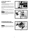
Fig. 29
A
B
B
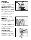
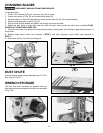
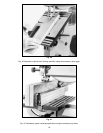
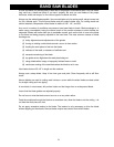
ADJUSTING BELT TENSION
If the drive belt on your band saw needs adjustment,
proceed as follows:
DISCONNECT MACHINE FROM POWER
SOURCE.
The belt (A) Fig. 29, drives the blade wheel pulley from
the motor pulley. The belt (A) is properly tensioned when
there is approximately 1/4" deflection in the center span
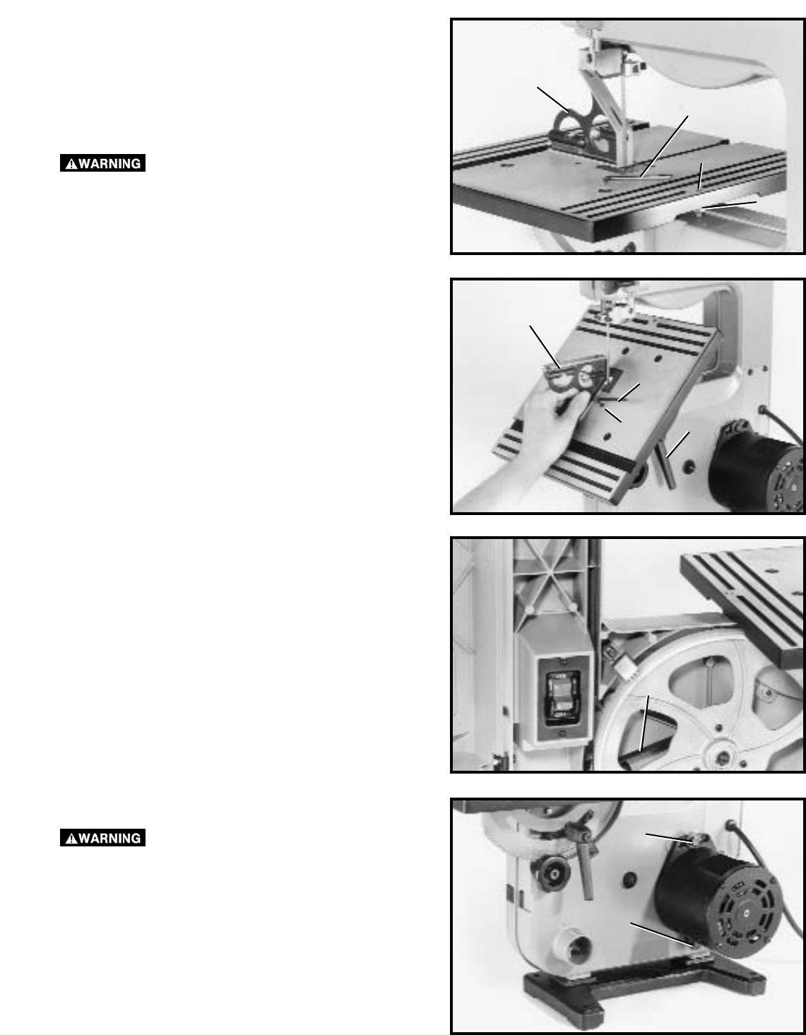
of the belt using light finger pressure. If belt tension
needs to be adjusted, loosen two screws (B) Fig. 30, and
rotate motor accordingly. Tighten screws (B) when
adjustment is completed.
Fig. 30