


14
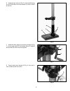
Fig. 24
C
E
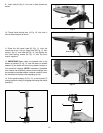
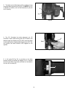
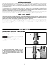
3. The table can be tilted right or left by pulling out and
removing table alignment pin (C) Fig. 24. NOTE: If pin (C)
is difficult to remove, turn nut (E) clockwise to pull pin
out of casting.
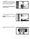
4. Fig. 25, illustrates the table alignment pin (C)
removed. Loosen table locking bolt (D), tilt table to the
desired angle and tighten bolt (D). When returning table
to the level position, replace table alignment pin (C). This
will position the table surface at 90 degrees to the
spindle.
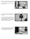
5. A tilt scale (E) Fig. 26, is provided on the table
bracket casting to indicate the degree of tilt. A witness
line and zero mark (F) are also provided on the table to
line up with the scale (E).
Fig. 25
Fig. 26
E
F
C
D