


15
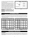
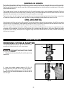
SPINDLE SPEEDS
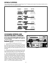
Twelve spindle speeds are available on the drill press. Fig. 27, illustrates which steps of the pulleys the belts must be
placed to obtain the twelve speeds available.
Fig. 27
SPINDLE CENTER
MOTOR
540
360
250
1090
590
410
1820
1280
650
3000
2180
1450
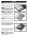
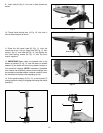
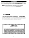
CHANGING SPEEDS AND
ADJUSTING BELT TENSION
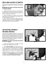
NOTE: A BELT POSITIONING SPEED CHART (E) FIG.
28, IS LOCATED ON THE INSIDE TOP COVER OF
THE DRILL PRESS.
DISCONNECT MACHINE FROM POWER
SOURCE.
1. Lift up the belt and pulley guard (A) Fig. 28.
2. Release belt tension by loosening tension lock knob
(B) Fig. 28, and the tension knob located on the other
side of the head casting and moving tension lever (C)
forward.pivoting the motor (D) toward the front of the
drill press.
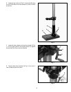
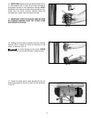
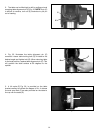
3. While holding the motor toward the front of the drill
press, position the belts (F) on the desired steps of the
motor and spindle pulleys, as shown in Figs. 27 & 28.
4. After the belts are positioned on the desired steps of
the motor and spindle pulleys, move motor (D) Fig. 28,
to the rear until the belt is properly tensioned and tighten
tension lock knob (B). The belt should be just tight
enough to prevent slipping. Excessive tension will
reduce the life of the belt, pulleys and bearings. Correct
tension is obtained when the belts (F) can be flexed
about 1" out of line midway between the pulleys.
Fig. 28
A
C
B
E
D
F