


16
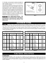
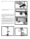
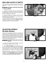
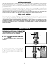
DRILLING HOLES TO DEPTH
Where a number of holes are to be drilled to exactly the
same depth, a depth stop is provided and is used as
follows:
DISCONNECT MACHINE FROM POWER
SOURCE.
1. Install bit in chuck.
2. Loosen lock screw (A) Fig. 29, and rotate pinion
assembly (B) until the pointer (C) lines up with the mark
on the scale (D) you wish the depth of the holes to be
drilled. Then tighten lock screw (A).
3. Place the material to be drilled on the drill press
table. Raise the drill press table until the material to be
drilled just touches the drill bit.
4. Drill a test hole to check the depth and adjust if
necessary. All holes will then be drilled to the exact
depth as indicated on scale (D) Fig. 29. NOTE: Scale (D)
is calibrated in both inches and millimeters.
Fig. 29
C
A
B
D
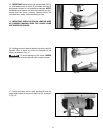
ADJUSTING SPINDLE
RETURN SPRING
The spindle is automatically returned to its upper most
position when the handle is released. It is recommended
that the handle be allowed to slowly return to the top
position after each hole has been drilled. This spring has
been properly adjusted at the factory and should not be
disturbed unless absolutely necessary. To adjust the
return spring, proceed as follows:
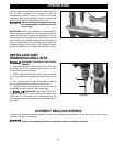
DISCONNECT MACHINE FROM POWER
SOURCE.
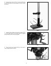
1. Loosen nuts (B) and (E) Fig. 30. Make sure spring
housing (A) stays engaged with head casting.
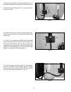
2. While FIRMLY HOLDING spring housing (A) Fig. 31
pull out housing and rotate it until boss (D) is engaged
with the next notch in the housing. Turn the housing
counterclockwise to increase or clockwise to decrease
spring tension. Turn nut (E) until it contacts spring
housing (A), then back nut (E) out a 1/4 turn from spring
housing (A). Tighten nut (B) against nut (E), to hold the
housing in place. IMPORTANT: Inside nut (E) should
not contact spring housing (A) when tightened.
Fig. 30
B
E
A
Fig. 31
D
E
B
A