


6. Reinstall the drive belt. Make sure the belt
is centered on the engine pulley and flywheel.
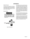
7. Slide the engine back into its original position
and adjust the belt tension, Figure 8.
For compressors equipped with poly-V-belts, the
proper tension is approximately 1/4 inch belt
deflection measured midway between the engine
pulley and flywheel when a 3 pound downward
force, or equivalent finger pressure, is applied at
that point.
For compressors equipped with standard V-belts
the proper tension for each belt is approximately
1/4 inch belt deflection measured midway between
the engine pulley and flywheel when a 4 pound
downward force, or equivalent finger pressure, is
applied at that point.
8. Hold the belt tension until the engine mount-
ing hardware can be tightened.
9. Torque the engine mounting bolts to 20
+3 foot-
pounds.
10. Reinstall the belt guard.
11. Connect the spark plug wire.
CHECK VALVE INSPECTION AND CLEANING
Remove and inspect the check valve at least once a
year and more often if the compressor is heavily
used. Moisture and other contaminates in the hot
compressed air will cause an accumulation of
carbon-like residue on the working parts. If the valve
has heavy carbon build-up, it should be replaced.
Use the following procedure to inspect, clean, or
replace the check valve:
1. Disconnect the spark plug wire and re-
lease all air pressure from the air tank.
2. Loosen the top and bottom tube nuts
and remove the outlet tube.
3. Unscrew the check valve (counterclock-
wise) from the air tank using a socket
wrench.
4. Check that the valve and disc moves freely
inside the check valve and that the spring
holds the disc in the upper closed position.
The check valve may be cleaned with a
solvent.
5. Apply pipe sealant to the check valve threads.
REPLACING DRIVE BELT (cont’d)
5. Slide the engine back into its original position
and adjust the belt tension, Figure 8.
For compressors equipped with standard V-belts,
the proper tension for each belt is approximately
1/4 inch belt deflection measured midway between
the engine pulley and flywheel when a 4 pound
downward force, or equivalent finger pressure, is
applied at that point.
6. Hold the belt tension until the engine mounting
hardware can be tightened.
7. Torque engine mounting bolts to 20
+3 foot-
pounds.
8. Reinstall the belt guard.
9. Connect the spark plug wire.
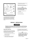
ENGINE PULLEY AND FLYWHEEL
ALIGNMENT
The engine pulley and flywheel must be aligned to
prevent excessive wear of the drive belt and to keep
the belt from coming out of the pulley and flywheel
grooves. Align the belts as follows:
Serious injury or damage may occur if
parts of the body or loose items get
caught in moving parts. Never operate
the compressor outfit with belt guard
removed. Remove belt guard only after
the spark plug had been disconnected.
1. Disconnect the spark plug wire and drain
all pressure from the air tank.
2. Remove the belt guard.
3. Loosen all engine mounting hardware and
slide the engine toward the compressor. Re-
move the drive belt.
4. Loosen the engine pulley set screw and move
the pulley toward or away from the engine until
the pulley aligns with the flywheel within 1/116
inch.
5. Torque the engine pulley set screw to 75 +5
inch-pounds.
PAGE 18