


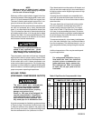


AIR LENGTH OF PIPE LINES IN FEET
cfm 25 50 75 100 150 200 250 300
1 - 5 1/2 1/2 1/2 1/2 1/2 1/2 1/2 1/2
10 1/2 1/2 1/2 1/2 1/2 1/2 1/2 1/2
15 1/2 3/4 3/4 3/4 3/4 3/4 3/4 3/4
20 3/4 3/4 3/4 3/4 3/4 3/4 3/4 3/4
25 3/4 3/4 3/4 3/4 1 1 1 1
30 3/4 3/4 3/4 1 1 1 1 1
35 3/4 3/4 1 1 1 1 1 1
40 3/4 1 1 1 1 1 1 1
50 1 1 1 1 1 1 1 1
60-70 1 1 1 1 1-¼ 1-¼ 1-¼ 1-¼
80-100 1-¼ 1-¼ 1-¼ 1-¼ 1-½ 1-½ 1-½ 1-½
Pipe sizes are in inches
PAGE 9
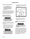
NOTE
Where a remote air intake is used, enlarge
the side of the air intake piping by one pipe
size for each 10 feet of length.
Stationary outfits must be bolted or lagged to the floor
to prevent movement. When lagging down, leave a mini-
mum of 1/8 inch between the bolt and support feet.
The use of vibration pads at each support foot is re-
quired to eliminate the possibility of tank rupture.
The flywheel side of the outfit should be placed toward
the wall and protected with a totally enclosed belt
guard. In no case should the flywheel be closer than
12 to 18 inches from the wall or other obstruction that
will interfere with the flow of air through the fan blade
flywheel. See Table 1 for recommended distances. The
area should allow space on all sides for air circulation
and for ease of normal maintenance.
The compressor outfit must not be op-
erated in any confined area where
heat from the outfit can not readily es-
cape. Damage to the outfit may result.
The compressor crankcase and head are designed
with fins which allow for proper cooling. Clean or blow
off the fins and any other parts of the compressor out-
fit that collect dust or dirt. A clean compressor runs
cooler and provides longer service. Do not place rags,
containers, or other material in or against the belt guard
which will obstruct ventilation openings necessary for
proper compressor operating temperatures.
AIR LINE PIPING
(STATIONARY COMPRESSOR OUTFITS)
The use of plastic pipe, soldered joint,
or failure to insure system capability
of flex joints and flexible hose can
result in mechanical failure, property
damage, and serious injury.
Plastic or PVC pipe is not designed for
use with compressed air. Regardless
of its indicated pressure rating, plastic
pipe can burst from air pressure. Use
only metal pipe for air distribution lines.
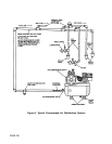
A typical compressed air distribution system as shown
in Figure 4, page 10 should be of sufficient pipe size
to keep the pressure drop between the supply and
point of use to a minimum. All pipes and fittings used
must be certified safe for the pressures involved.
Pipe thread sealant must be used on all threads, and
all joints are to be made up tight, since small leaks in
the piping system are the largest single cause of high
operating costs.
All piping should be sloped to an accessible drain
point and all outlets should be taken from the top of
the main distribution air line so that moisture cannot
enter the outlet.
The main distribution air line should not be smaller
than the compressor air discharge valve outlet. A
smaller line will restrict the flow of air. For long air
lines, refer to Table 2, Pipe Sizes for Compressed
Air Lines, for recommended pipe sizes. It is recom-
mended that a flexible coupling be installed between
the air discharge valve outlet and main air distribu-
tion line to allow for vibration.
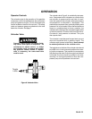
To remove entrained dirt, oil and water, install separa-
tor in the main distribution line, a sufficient distance
from the compressor. This will allow the air to cool to
room temperature before passing through the separa-
tor.
Additional separators or filter may be used depend-
ing on the application.
NOTE
For underground installation, bury air
lines below the frost line and avoid
pockets where condensation can
gather and freeze. Apply pressure be-
fore underground lines are covered
to make sure all pipe joints are free
from leaks.
Table 2 Pipe Sizes for Compressed Air Lines