


PAGE 6
You have purchased a complete compressor outfit con-
sisting of an air compressor, ASME approved air tank,
gasoline engine, and associated controls and instru-
ments. The compressor outfit you have selected is a
two stage stationary outfit.
Your new compressor can be used for operating paint
sprayers, air tools, grease guns, air brushes, caulking
guns, and sand blasters, spraying weed killer and
insecticides, etc. An air pressure regulator may be
necessary for some of these
The gasoline engine uses a pulley and drive belt to
drive the compressor flywheel. The flywheel turns the
compressor crankshaft causing the up and down move-
ment of the pistons in the cylinder; this up and down
movement draws and compresses the air.
On the down stroke of the piston, air is drawn in through
the air intake. The exhaust valves remain closed. On
the up stroke of the piston, both the valves are closed
and air is compressed in the cylinder. As pressure
builds in the cylinder the exhaust valve opens and the
compressed air is forced out of the cylinder through
the check valve and into the air tank. This process
continues until the air pressure reaches maximum tank
pressure.
Working air pressure becomes available when the com-
pressor has raised the tank pressure above that re-
quired at the air discharge valve. The air intake must
be kept clear of all obstructions which could interfere
with air delivery to the compressor.
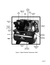
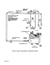
All gasoline compressor outfits are continuously run-
ning outfits controlled by tank pressure. At maximum
applications. Refer to Figure 1 for a photograph of
the compressor and to identify the major components
of the compressor.
A regularly scheduled program of preventive mainte-
nance is necessary to insure the long life that has been
designed into your DeVilbiss compressor outfit. This
instruction manual, along with regular maintenance
will maintain your compressor outfit in good working
order. Before operating or performing any maintenance
on your outfit, refer to these publications.
tank pressure the unloader valve exhausts air to at-
mosphere (blowoff); tank pressure closes the check
valve retaining air pressure inside the tank. When tank
pressure drops to a pre-determined pressure, the
unloader valve closes, and air pressure opens the
check valve allowing compressed air into the tank. As
maximum tank pressure is reached, if the unloader
valve malfunctions and compressed air is not ex-
hausted at or near its blowoff setting, the air tank safety
valve will protect the air tank against high pressure by
popping at its factory set pressure. The safety valve
popping pressure is slightly higher than the unloader
valve blowoff pressure.
This compressor outfit is equipped with a gas saving
throttle control device. When maximum tank pressure
is reached and the unloader valve opens the throttle
control is also activated, The throttle control holds the
engine at a factory set idling speed until air pressure
in the tank drops to reset or minimum tank pressure.
At reset pressure when the unloader valve closes the
throttle control is reactivated and the engine acceler-
ates to full throttle.
GENERAL INFORMATION
DESCRIPTION OF OPERATION