


English
10
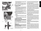
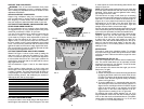
SUPPORT FOR LONG PIECES
WARNING: Turn off tool and disconnect from power
source before attempting to move it, changing accesso-
ries or making any adjustments accept as written in laser
adjustment instructions.
ALWAYS SUPPORT LONG PIECES
Support long workpieces using any convenient means
such as sawhorses or similar devices to keep the ends
from dropping. For best results, use the DW7080 exten-
sion work support to extend the table width of your saw.
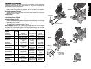
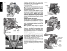
CUTTING PICTURE FRAMES, SHADOW BOXES AND
OTHER FOUR SIDED PROJECTS
To best understand how to make the items listed here,
we suggest that you try a few simple projects using scrap
wood until you develop a “FEEL” for your saw.
Your saw is the perfect tool for mitering corners like the
one shown in Figure 17. Sketch A in Figure 17 shows
a joint made by using the bevel adjustment to bevel the
edges of the two boards at 45° each to produce a 90
degree corner. For this joint the miter arm was locked in
the zero position and the bevel adjustment was locked
at 45°. The wood was positioned with the broad flat side
against the table and the narrow edge against the fence.
The cut could also be made by mitering right and left with
the broad surface against the fence.
CUTTING TRIM MOLDING AND OTHER FRAMES
Sketch B in Figure 17 shows a joint made by setting the
miter arm at 45° to miter the two boards to form a 90°
corner. To make this type of joint, set the bevel adjustment
to zero and the miter arm to 45°. Once again, position the
wood with the broad flat side on the table and the narrow
edge against the fence.
The two sketches in Figure 17 are for four sided objects
only.
As the number of sides changes, so do the miter and
bevel angles. The chart below gives the proper angles for
a variety of shapes. The chart assumes that all sides are
of equal length. For a shape that is not shown in the chart,
use the following formula. 180° divided by the number of
sides equals the miter or bevel angle.
- EXAMPLES -
NO. SIDES ANGLE MITER OR BEVEL
4 45°
5 36°
6 30°
7 25.7°
8 22.5°
9 20°
10 18°
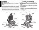
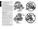
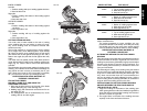
CUTTING COMPOUND MITERS
A compound miter is a cut made using a miter angle and a
bevel angle at the same time. This is the type of cut used
to make frames or boxes with slanting sides like the one
shown in Figure 18.
NOTE: If the cutting angle varies from cut to cut, check that
the bevel clamp knob and the miter lock knob are securely
tightened. These knobs must be tightened after making
any changes in bevel or miter.
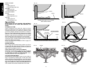
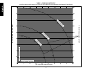
The chart shown on page 15 will assist you in selecting
the proper bevel and miter settings for common compound
miter cuts. To use the chart, select the desired angle “A”
(Figure 19) of your project and locate that angle on the
appropriate arc in the chart. From that point follow the
chart straight down to find the correct bevel angle and
straight across to find the correct miter angle.
Set your saw to the prescribed angles and make a few trial
cuts. Practice fitting the cut pieces together until you devel-
op a feel for this procedure and feel comfortable with it.
Example: To make a 4 sided box with 26° exterior angles
(Angle A, Figure 19), use the upper right arc. Find 26°
on the arc scale. Follow the horizontal intersecting line
to either side to get miter angle setting on saw (42°).
Likewise, follow the vertical intersecting line to the top or
bottom to get the bevel angle setting on the saw (18°).
Always try cuts on a few scrap pieces of wood to verify
settings on saw.
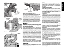
MITER SCALE
The scale is used when calculating angles. To calculate
the proper miter angle, divide 180° by the number of sides
of the box or frame. Refer to the chart on page 8 for some
examples.
VERNIER SCALE (FIG. 23, 24)
Your saw is equipped with a vernier scale for added preci-
sion. The vernier scale allows you to accurately set miter
angles to the nearest 1/4° (15 minutes). To use the vernier
scale follow the steps listed below.
(As an example, let’s assume that the angle you want to
miter is 24-1/4° right).
1. Turn off miter saw.
2. Set the miter angle to the nearest whole degree desired
by aligning the center mark in the vernier scale, shown
in Figure 23, with the whole degree number etched in
the miter scale. Examine Figure 23 closely; the setting
shown is 24º right miter.
3. To set the additional 1/4°, squeeze the miter arm lock
and carefully move the arm to the RIGHT until the 1/4
degree vernier mark aligns with the CLOSEST degree
mark on the miter scale. In our example, the closest
degree mark on the miter scale happens to be 25°.
Figure 24 shows a setting of 24-1/4° right miter.
For settings that require partial degrees (1/4, 1/2, 3/4°)
align the desired vernier mark with the CLOSEST degree
mark on the miter scale, as described above. (The plastic
vernier plate is inscribed with marks for 1/4, 1/2, 3/4 and
1°. Only the 1/2° is numerically labeled.)
FIG. 18
FIG. 19
FIG. 17
A.
B.
ANGLE “A”
FIG. 21
FIG. 20
MITER
SCALE