


English
6
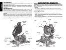
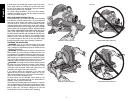
5. Keeping the button depressed, use the other hand and
the wrench provided to loosen the blade screw. (Turn
clockwise, left-hand threads)
6. Remove the blade screw, outer clamp washer, and
blade. The 1" (25.4 mm) blade adapter, if used, and
the inner clamp washer, may be left on the spindle.
NOTE: For blades with a blade hole of 5/8" (15.88 mm),
the 1" (25.4 mm) blade adapter is not used.
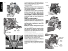
Installing a Blade
1. Unplug the saw.
2. With the arm raised, the lower guard held open and
the pivot plate raised, place the blade on the spindle,
onto the blade adapter [if using a blade with a 1"
(25.4 mm) diameter blade hole] and against the inner
clamp washer with the teeth at the bottom of the blade
pointing toward the back of the saw.
3. Assemble the outer clamp washer onto the spindle.
4. Install the blade screw and, engaging the spindle lock,
tighten the screw firmly with wrench provided. (Turn
counterclockwise, left-hand threads)
NOTE: When using blades with a 5/8" (15.88 mm) diam-
eter blade hole, the blade adapter will not be used and
should be stored in a safe place for future use.
5. Return the guard bracket to its original position and
firmly tighten the guard bracket screw to hold bracket
in place.
WARNING:
• The guard bracket must be returned to its original
position and the screw tightened before activating
the saw.
• Failure to do so may allow the guard to contact the
spinning saw blade resulting in damage to the saw
and severe personal injury.
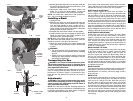
Transporting the Saw
WARNING: Turn off tool and disconnect from power
source before attempting to move it, changing acces-
sories or making any adjustments accept as written in
laser adjustment instructions.
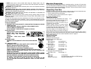
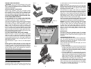
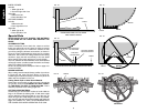
In order to conveniently carry the miter saw from place to
place, a carrying handle has been included on the top of
the saw arm, as shown in Figure 3. To transport the saw,
lower the arm and depress the lock down pin shown in
Figure 4.
Adjustments
WARNING: Turn off tool and disconnect from power
source before attempting to move it, changing acces-
sories or making any adjustments accept as written in
laser adjustment instructions.
NOTE: Your miter saw is fully and accurately adjusted at
the factory at the time of manufacture. If readjustment due
to shipping and handling or any other reason is required,
follow the steps below to adjust your saw.
FIG. 5
GUARD
GUARD
BRACKET
SCREW
WRENCH
FIG. 4
LOCK
DOWN
PIN
FIG. 6
BLADE
INNER CLAMP
WASHER
BLADE
ADAPTER
OUTER
CLAMP
WASHER
BLADE
SCREW
Once made, these adjustments should remain accurate.
Take a little time now to follow these directions carefully to
maintain the accuracy of which your saw is capable.
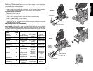
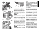
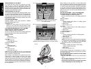
MITER SCALE ADJUSTMENT
Place a square against the saw’s fence and blade, as
shown in Figure 7. (Do not touch the tips of the blade teeth
with the square. To do so will cause an inaccurate mea-
surement.) Unlock miter lock lever (see Fig. 8) and swing
the miter arm until the miter detent locks it at the 0˚ miter
position. Do not lock miter lock lever. If the saw blade is not
exactly perpendicular to the fence, loosen the three screws
that hold the miter scale to the base (shown in Fig. 8) and
move the scale/miter arm assembly left or right until the
blade is perpendicular to the fence, as measured with the
square. Retighten the three screws. Pay no attention to the
reading of the miter pointer at this point.
MITER POINTER ADJUSTMENT
Unlock miter lock lever and squeeze the miter detent
to move the miter arm to the zero position, as shown in
Figure 8. Unlock the miter lock lever to allow the miter
detent to snap into place as you rotate the miter arm past
zero. Observe the pointer and miter scale through the
viewing opening shown in Figure 9. If the pointer does not
indicate exactly zero, loosen the pointer screw, adjust the
pointer to 0˚ and retighten.
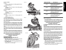
BEVEL SQUARE TO TABLE
To align the blade square to the rotary table, lock the arm
in the down position. Place a square against the blade
taking care to not have the square on top of a tooth, as
shown in Figure 10B. Loosen the Bevel Clamp Knob so
that you can move the Bevel Arm. Move the Bevel Arm
as necessary so that the blade is at 0° bevel to the table.
If the Bevel Arm needs adjustment, loosen the lock nut on
the right side Bevel Stop as shown in Figure 11, and adjust
the stop screw as necessary. Hold the stop screw in place
and tighten the lock nut.
BEVEL POINTER
If the bevel pointer does not indicate zero, loosen the screw
that holds it in place and move the pointer as necessary.
SUGGESTION: For accuracy, set the top edge so that it
aligns with zero.
BEVEL STOP
To set the 45° bevel stop shown in Figure 12, first loosen
the left side fence clamping knob and slide the left side
fence as far as it will go to the left. Move the arm to the
left until it stops on the left bevel stop screw. If the bevel
pointer does not indicate exactly 45°, loosen the left side
bevel stop lock nut and turn the screw downwards. Move
the arm to the left and tighten the bevel clamp knob firmly
when the bevel pointer indicates exactly 45°. Adjust the
left side bevel stop screw upwards until it firmly touches
the bevel stop. Retighten the nut while holding the screw
from turning.