


English
5
ACCESSORIES
Recommended accessories for use with your tool are available for purchase from your local
dealer or authorized service center.
WARNING: Since accessories, other than those offered by DEWALT, have not been
tested with this product, use of such accessories with this tool could be hazardous. To
reduce the risk of injury, only D
EWALT, recommended accessories should be used with
this product.
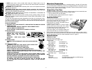
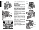
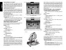
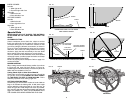
Bench Mounting
Holes are provided in all four feet to facilitate bench mounting, as shown in Figure 2. (Two
different sized holes are provided to accommodate different sizes of screws. Use either
hole, it is not necessary to use both.) Always mount your saw firmly to prevent movement.
To enhance the tool’s portability, it can be mounted to a piece of 1/2" (12.7 mm) or thicker
plywood which can then be clamped to your work support or moved to other job sites and
reclamped.
NOTE: If you elect to mount your saw to a piece of plywood, make sure that the mounting
screws don’t protrude from the bottom of the wood. The plywood must sit flush on the work
support. When clamping the saw to any work surface, clamp only on the clamping bosses
where the mounting screw holes are located. Clamping at any other point will surely inter-
fere with the proper operation of the saw.
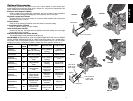
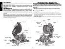
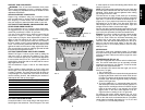
FIG. 3
GUARD
RIGHT SIDE
FENCE
MITER LOCK
LEVER
MITER SCALE
BENCH
MOUNTING
HOLES
LEFT SIDE FENCE
CLAMPING KNOB
OPERATING
HANDLE
TABLE
BASE
HOLES FOR
EXTENSION KIT
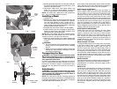
FIG. 2
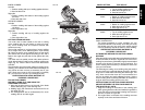
TRIGGER
SWITCH
CARRYING
HANDLE
SPINDLE LOCK
BUTTON
LEFT SIDE
FENCE
MOTOR
HOUSING
BEVEL
SCALE
MITER
DETENT
MITER
SCALE
HAND
INDENTATION
BEVEL CLAMP
KNOB
DUST
SPOUT
MOTOR
END CAP
IMPORTANT SAFETY INSTRUCTIONS
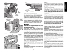
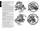
Changing or Installing a New Saw Blade (Fig. 5, 6)
WARNING: Turn off tool and disconnect from power source before attempting to
move it, changing accessories or making any adjustments accept as written in laser
adjustment instructions.
CAUTION:
• Never depress the spindle lock button while the blade is under power or coasting.
• Do not cut ferrous metal (containing iron or steel) or masonry or fiber cement product
with this miter saw.
Removing the Blade
1. Unplug the saw.
2. Raise the arm to the upper position and raise the lower guard as far as possible.
3. Loosen, but do not remove guard bracket screw until the bracket can be raised far
enough to access the blade screw. Lower guard will remain raised due to the position
of the guard bracket screw.
4. Depress the spindle lock button (Fig. 3) while carefully rotating the saw blade by hand
until the lock engages.
WRENCH
MITER
DETENT
OVER RIDE