


English
8
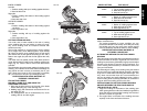
SWITCH
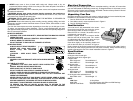
To turn the saw on, depress the trigger switch shown in
Figure 14. To turn the tool off, release the switch. There
is no provision for locking the switch on, but a hole is
provided in the trigger for insertion of a padlock to lock
the saw off.
CUTTING WITH YOUR SAW
NOTE: Although this saw will cut wood and many non-fer-
rous materials, we will limit our discussion to the cutting
of wood only. The same guidelines apply to the other
materials. DO NOT CUT FERROUS (IRON AND STEEL)
MATERIALS OR MASONRY WITH THIS SAW. Do not
use any abrasive blades.
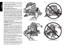
CROSSCUTS
Cutting of multiple pieces is not recommended but can
be done safely by ensuring that each piece is held firmly
against the table and fence. A crosscut is made by cutting
wood across the grain at any angle. A straight crosscut is
made with the miter arm at the zero degree position. Set
the miter arm at zero, hold the wood on the table and firmly
against the fence. Turn on the saw by squeezing the trig-
ger switch shown in Figure 14.
When the saw comes up to speed (about 1 second) lower
the arm smoothly and slowly to cut through the wood. Let
the blade come to a full stop before raising arm.
Miter crosscuts are made with the miter arm at some angle
other than zero. This angle is often 45° for making corners,
but can be set anywhere from zero to 50° left or right. After
selecting the desired miter angle, be sure to tighten the
miter lock lever. Make the cut as described above.
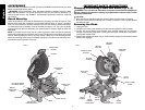
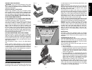
BEVEL CUTS
A bevel cut is a crosscut made with the saw blade at a
bevel to the wood. In order to set the bevel, loosen the
bevel clamp knob and move the saw to the left as desired.
(It is necessary to move the left side of the fence to
allow clearance). Once the desired bevel angle has been
set, tighten the bevel clamp knob firmly.
Bevel angles can be set from 3° right to48° left and can be
cut with the miter arm set between zero and 50° right or
left. Ensure the fence has been adjusted properly. When
cutting left bevel, or right miter compound cuts, it will be
necessary to remove the adjustable fence.
QUALITY OF CUT
The smoothness of any cut depends on a number of vari-
ables. Things like material being cut, blade type, blade
sharpness and rate of cut all contribute to the quality of
the cut.
When smoothest cuts are desired for molding and other
precision work, a sharp (60 - 80 tooth carbide) blade and a
slower, even cutting rate will produce the desired results.
Ensure that material does not creep while cutting. Clamp it
securely in place. Always let the blade come to a full stop
before raising arm.
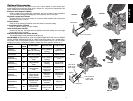
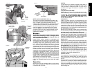
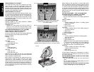
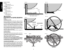
MITER LOCK ADJUSTMENT (FIG. 15)
The miter lock rod should be adjusted if the table of the
saw can be moved when the miter lock handle is locked
down. To adjust, put the miter lock handle in the up
position. Using a slotted screwdriver, adjust the lock rod in
1/8 clockwise turn increments to increase the lock force.
To ensure the miter lock is functioning properly, re-lock
miter lock handle to a non-detent miter angle. Tighten
set screw. NOTE: Some models may have a set screw
as shown in Figure 15. Using a 3/32 hex wrench, loosen
the set screw on the pivot pin. Tighten set screw after
adjustment is complete.
Brushes
WARNING: Turn off tool and disconnect from power
source before attempting to move it, changing acces-
sories or making any adjustments accept as written in
laser adjustment instructions.
Inspect carbon brushes regularly by unplugging tool,
removing the motor end cap (Fig. 2), lift the brush spring
and withdraw the brush assembly. Keep brushes clean
and sliding freely in their guides. Always replace a used
brush in the same orientation in the holder as it was prior
to its removal. Carbon brushes have varying symbols
stamped into their sides, and if the brush is worn down to
approximately 1/2" (127 mm), the spring will no longer exert
pressure and they must be replaced. Use only identical
D
EWALT brushes. Use of the correct grade of brush is
essential for proper operation of electric brake. New brush
assemblies are available at D
EWALT service centers. The
tool should be allowed to “run in” (run at no load) for 10
minutes before use to seat new brushes. The electric brake
may be erratic in operation until the brushes are properly
seated (worn in). Always replace the brush inspection cap
after inspection or servicing the brushes.
While “running in” DO NOT TIE, TAPE, OR OTHER WISE
LOCK THE TRIGGER SWITCH ON. HOLD BY HAND
ONLY.
Operation
Plug the saw into any household 60 Hz power source.
Refer to the nameplate for voltage. Be sure the cord will
not interfere with your work.
FIG. 14
TRIGGER
SWITCH
HOLE FOR PADLOCK
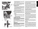
LEFT SIDE
FENCE
CLAMPING
KNOB
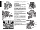
FIG. 13
LEFT SIDE
BEVEL STOP
SCREW
STOP
SCREW
LOCK
NUT
FIG. 12
BEVEL
POINTER
BEVEL
CLAMP
KNOB
FIG. 15
SET SCREW
SLOTTED
ADJUSTMENT
ROD