


6
MODEL 396R pH/ORP SECTION 2.0
INSTALLATION
SECTION 2.0
INSTALLATION
2.1 UNPACKING AND INSPECTION. Inspect the outside
of the carton for any damage. If damage is detected,
contact the carrier immediately. Inspect the instrument
and hardware. Make sure all items in the packing list
are present and in good condition. Notify the factory if
any part is missing.
NOTE
If the sensor is to be stored, the protective
boot should be filled with either KCl elec-
trolyte solution or pH 4.0 buffer solution
and replaced on sensor tip until ready to
use.
NOTE
Save the original packing cartons and
materials as most carriers require proof of
damage due to mishandling, etc. Also, if it
is necessary to return the instrument to the
factory, you must pack the instrument in the
same manner as it was received. Refer to
Section 8.0 for instructions.
WARNING
Glass electrode must be wetted at all times (in storage
and in line) to maximize sensor life.
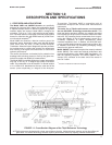
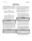
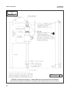
2.2 MECHANICAL INSTALLATION. The Model 396R
Sensor may be installed through a weldalet or in a pipe
tee or “Y”, as shown in Figure 2-1, when used with a
ball valve. Insert the end of the sensor to a depth
sufficient to ensure that the glass bulb is continuously
wetted by the process fluid. The Model 396R can also
be inserted directly into the process without the use of
a ball valve for appli cations not requiring continuous
operation during sensor maintenance.
CAUTION
Allow sufficient room for safe retraction and insertion of
the sensor. Personnel should have room for stable foot-
ing while performing removal or insertion of the sensor.
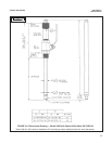
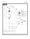
The sensor must be mounted within 10-90 degrees of
the horizontal with the tip pointed downward, thus
keeping air bubbles off of the pH sensitive glass bulb.
Bubbles settled on the glass bulb disrupt the electrical
continuity between the pH sensitive glass and the sil-
ver/silver chloride measuring element.
If the retraction version is to be installed without a ball
valve follow the installation procedure for insertion
service (Section 2.2.2). Perform the following steps for
sensor installation through a ball valve:
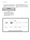
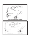
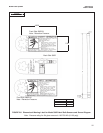
2.2.1 INSTALLATION THROUGH BALL VALVE.
1. Carefully remove the liquid filled rubber boot which
protects the glass electrode and keeps the liquid
junction wet during shipping and storage. Discard
the liquid and boot. Make sure the lubricated
O-ring is in place in the groove inside the male
connector on the sensor body.
CAUTION
Buffer solution, in the protective boot, may cause skin
or eye irritation.
2. With the male connector on the sensor’s body,
insert the sensor into the ball valve until it gently
touches the closed valve. The molded electrode
guard will protect the glass bulb from breakage.
3. Thread the male connector body tightly into the
ball valve assembly. DO NOT tighten the hex nut
on the male connector body; doing so would not
allow the sensor to be inserted through the ball
valve.
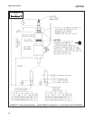
4. Pull back hard on the sensor assembly, as if trying
to remove the sensor, to be certain that the sensor
cannot come free of the ball valve assembly. The
built-in retraction stop will butt against the shoul-
der of the male connector if properly installed.
CAUTION
The sensor must be captured by the valve assembly
and the male connector so that it cannot be blown
free by process pressure if mishandled during inser-
tion or retraction.
5. After confirming that the sensor assembly is prop-
erly secured by the valve assembly, the valve may
be opened and the sensor positioned into the
process at the desired depth and orientation.