


33
MODEL 396R pH/ORP SECTION 6.0
MAINTENANCE
4. Following the caution above, wash the glass bulb
in dilute 5% hydrochloric acid solution and then
rinse it thoroughly in tap water. Replace the sen-
sor if it cannot be cleaned. If the glass bulb
appears clean, proceed to step 5.
5. Buffer calibrate the sensor (Refer to Section 5.0). If
the sensor appears to respond sluggishly to pH
change, soaking it overnight in a weak acid solution
(5% hydrochloric acid) may improve its response. Be
sure to follow the CAUTION above and to rinse the
sensor’s tip thoroughly with tap water. If the sensor
will not calibrate, it must be replaced.
6.4 Cleaning Platinum Electrode. The electrode is
never exposed to these undesirable compounds. In the
event poisoning is suspected, the electrode can be
restored to normal operation by simply cleaning the plat-
inum electrode with baking soda. Polish it by rubbing it
with a damp paper towel and baking soda until a bright,
shiny appearance is attained.
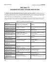
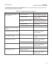
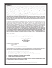
6.5 Automatic Temperature Compensator. The tem-
perature compensator element is temp erature sensi-
tive and can be checked with an ohmmeter.
Resistance increases with temperature.
The 3K element will read 3000 ohms ± 1% at 25°C
(77°F) and a Pt-100 will read 110 ohms. Resistance
varies with temperature for a 3K and Pt-100 element
and can be determined according to Table 6-2 or the
following formula:
R
T
=R
o
[l+R
1
(T-20)]
Where R
T
= Resistance
T = Temperature in °C
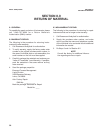
Refer to Table 6-1 for R
o
and R
1
values:
TABLE 6-1
R
o
and R
1
VALUES FOR TEMPERATURE
COMPENSATION ELEMENTS
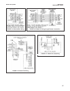
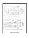
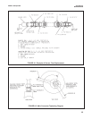
6.6 Sensor Tube Replacement When Used With A
Sensor Head Junction Box. Replace ment of the
retraction versions sensor tube assembly involves the
removal and installation of two sets of male connectors:
One at the process end of the sensor, and the other at
the junction box end (See Figures 6-1, 6-2). Refer to
Section 6.2 for proper removal of the sensor from
process.
1. Remove sensor from process before proceeding.
The junction box with attached male connector
must be recovered from the old sensor for reuse.
Unscrew the junction box cover and set aside.
Disconnect electrical connections from printed cir-
cuit board inside junction box. Disconnect BNC
connector to preamp. Unscrew hex nut (D) from
male connector body (C). Separate junction box
from used sensor. Set aside.
2. Pry off split ferrule from sensor and set aside for
reuse. Remove hex nut (D) and set aside for
reuse. Check that the internal O-ring is in place in
the male connector body (C) attached to the junc-
tion box.
3. Remove hex nut (B) from male connector body (A)
at process end of sensor and set aside. Slide the
Teflon ferrule and the male connector off sensor in
the direction of junction box and set
NOTE
If stainless steel ferrule was used, male
connector body (A) will have to be dis -
carded with the sensor tube.
Resistance
Temperature °C (Ohms) ±1%
3K PT-100
0 2670 100.0
10 2802 103.8
20 2934 107.7
25 3000 109.6
30 3066 111.5
40 3198 115.4
50 3330 119.2
60 3462 123.1
70 3594 126.9
80 3726 130.8
90 3858 134.6
100 3990 138.5
Temperature
Compensation Element
R
o
R
1
3K 2934 .0045
PT-100 107.7 .00385
TABLE 6-2
TEMPERATURE vs RESISTANCE OF AUTO
T.C. ELEMENTS