


14
MODEL 396R pH/ORP SECTION 3.0
WIRING MODEL 396R
SECTION 3.0
WIRING MODEL 396R
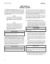
WIRING MODEL 396R.
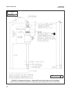
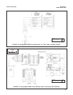
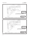
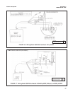
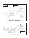
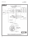
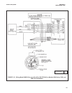
Make electrical connections as shown on Figures 3-1
through 3-15 using the following guidelines. For wiring
Model 396RVP, see Section 4.0.
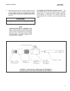
1. Pay particular attention to the analyzer or trans-
mitter model number when following details on the
wiring diagrams to ensure that the connections are
made to the proper terminals.
2. Use Rosemount custom cable Part Number
9200273 for interconnect.
3. The maximum distance from the sensor to the
analyzer is 15 ft without an integral preamplifier.
4. Signal cable should be run in a dedicated conduit
and should be kept away from AC power lines.
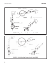
NOTE
For maximum EMI/RFI protection when wiring
from the sensor to the junction box, the outer
braid of the sensor should be connected to the
outer braided shield of the extension cable.
The outer braid of the extension cable to the
instrument must be terminated at earth ground
or by using an appropriate metal cable gland
fitting, that provides a secure connection to the
instrument cable.
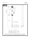
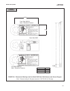
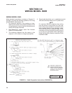
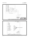
FIGURE 3-1. Cable Preparation Instructions (PN 9200274)
WARNING: IF INNER BLACK
CONDUCTIVE SHEATH IS IN
CONTACT WITH THE EXPOSED
LEADS, OR IS NOT PREPARED
PROPERLY, IT MAY CAUSE AN
ELECTRICAL SHORT.
DWG. NO. REV.
40396R24 A