


34
4. Discard used O-ring from male connector body
(A). Coat new O-ring with a thin film of the O-ring
lubricant provided. Position it in the machined O-
ring groove in place of the discarded O-ring.
CAUTION
Make sure lubricant does not contact any part of the
sensor tip particularly the glass bulb.
5. Cover the 1" MNPT pipe threads of the male con-
nector body (A) with Teflon tape (not provided) to
protect them from galling during reinstallation.
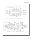
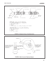
6. Pass the wires from the new sensor through the
process end male connector (A). Make sure that
the beveled edge of the ferrule faces the process
end of the sensor. Snug the hex nut (B) to keep it
in place. Do not tighten down fully on the hex nut
at this time.
7. Pass the wires from the new sensor through the
hex nut (D), the split ferrule (from the old sensor),
male connector body (C), O-ring, and through the
junction box from the “neck” opening and out to
the printed circuit board in the junction box. Butt
the ferrule’s beveled edge and the sensor
tube against the junction male connector (C).
Screw the hex nut (D) by hand until the tube is
“locked” into the male connector body. Make sure
that the male connector body (C) is sufficiently
tightened. The sensor will “click” into place by
pulling the sensor tube away from the junction
box, but will not move from side to side or pull
clear of the male connector. If the sensor tube is
correctly attached to the junction box, wrench
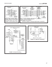
tighten hex nut (D) on male connector body (C)
(see Figure 6-1). Do not put the sensor tube in a
vise or use a pipe wrench to tighten the hardware
as these will damage the sensor. If sensor tube is
not correctly attached to the junction box, loosen
hex nut (D) and repeat.
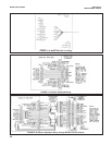
8. Connect the sensor wires to the terminals on the
printed circuit board in the junction box in the manner
recommended on the junction box cover,and
reattach the BNC connector to the preamp. Screw on
the cover of the junction box aside. Discard sensor
tube.
9. Insert the sensor in the process fitting. Stop it
against the closed ball valve. Slide the process-
end male connector down the sensor tube to mate
with the process fitting. Tighten the male connec-
tor into the process fitting.
10. Pull back hard on the sensor assembly, as if trying
to remove the sensor, to be certain that the sensor
cannot come free from the valve assembly and
male connector. The built-in retraction stop collar
at the end of the sensor will butt against the shoul-
der of the male connector.
11. Open ball valve and position the sensor at the
desired insertion depth and orientation. Using a
crescent or open end wrench, tighten the hex nut
(B) to secure the sensor in place. See Figure 6-2.
NOTE
A stainless steel ferrule is available if the
Teflon ferrule does not adequately grip, be
careful and avoid over tightening. This can
damage the sensor tube.
CAUTION
If the male connector leaks during insertion or retrac-
tion, replace the O-Ring (PN 9550099) in the male
connector body (A).
If the sensor is to be stored, the rubber boot should be
filled with 7pH buffer solution and replaced on sensor
tip until ready to use.
MODEL 396R pH/ORP SECTION 6.0
MAINTENANCE