


32
6.1 Maintenance. The Model 396R Sensor is a dis-
posal type sensor and therefore requires minimum
maintenance. The sensor should be removed from the
process periodically and checked in buffer solutions. If
the sensor will not calibrate, refer to your
analyzer/transmitters instruction manual for proper test
procedures. If the sensor has failed, it should be dis-
carded and replaced.
6.2 Sensor Removal. Please refer to the appropriate
paragraph for instructions regarding removal of the
sensor for periodic maintenance.
6.2.1 Retractable Version.
WARNING
System pressure may cause the sensor to blow out with
great force unless care is taken during removal. Make
sure the following steps are adhered to.
A. Model 396R-21 (21” tube)
1. Be certain system pressure at the sensor is below
64 psig (542 kPa) before proceeding with the
retraction. It is also recommended that the per-
sonnel wear a face shield and have a stable foot-
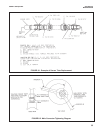
ing. Refer to Figure 6-1. Push in on the sensor
end or the top of the J-box and slowly loosen the
hex nut (B) of the process end male connector (A).
B. Model 396R-25 (36” tube)
2. Be certain that pressure at the sensor is below 35
psig (343 KPa) before proceeding with the retrac-
tion. It is also recommended that the personnel
wear a face shield and have a stable footing.
Refer to Figure 6-1. Push in on the sensor end or
the top of the J-box and slowly loosen the hex nut
(B) of the process end male connector (A).
CAUTION
Do not remove nut at this time.
3. When the hex nut is loose enough, slowly ease
the sensor back completely until the retraction
stop collar is reached.
CAUTION
Failure to withdraw the sensor completely may result
in damage to the sensor when the valve is closed.
4. Close the ball valve slowly. If there is resistance,
the valve may be hitting the sensor. Double check
that the sensor has been retracted to the retrac-
tion stop collar.
WARNING
Before removing the sensor from the ball valve, be
absolutely certain that the ball valve is fully closed.
Leakage from the male connector threads may indicate
that the male connector is still under pressure. Leakage
through a partially open valve could be hazardous, how-
ever with the ball valve closed, some residual process
fluid may leak from the connector's pipe threads.
5. The Male Connector Body (A) may now be com-
pletely unthreaded from the reducing coupling and
the sensor removed for servicing.
CAUTION
If the male connector leaks during insertion or retrac-
tion, replace the O-ring (PN 9550099) in the male
connector A.
6.3 pH Electrode Cleaning. If the electrode is coated
or dirty, it may be cleaned as follows:
1. Remove the sensor from process as instructed in
Section 6.2.
2. Wipe the glass bulb with a soft, clean, lint free
cloth or tissue. If this does not remove the dirt or
coating, proceed to step 3. If the sensor appears
to be clean, go to step 5.
3. Wash the glass bulb in a strong detergent solution
and thoroughly rinse with tap water. If the bulb still
appears to have a coating, proceed to step 4.
CAUTION
The solution used in the following step is an acid and
should be handled with care. Follow the directions of
the acid manufacturer. Wear the proper protective
equipment. Do not let the solution come in contact
with skin or clothing. If contact with the skin is made,
immediately rinse with clean water.
MODEL 396R pH/ORP SECTION 6.0
MAINTENANCE
SECTION 6.0
MAINTENANCE