


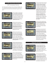
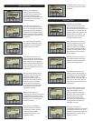
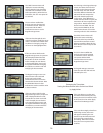
The next screen gives the user
a choice to set the 4mA or 20mA
values or to Exit the procedure.
Here the user will select the 4mA
menu position.
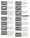
The HART Communicator requests
the user to set the Level (or
Interface) to the position that is
to provide the 4mA loop current
output. When that has been done,
the user must press OK to continue
with the procedure.
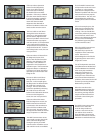
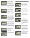
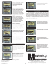
The HART Communicator then
requests a measurement reading
from the transmitter indicating
the digital value at this range
position. The user then has the
option of setting this value as
the lower range value, getting an
update of the digital reading from
the transmitter or leaving the 4mA
range point as it was.
If the user accepts the
measurement value as the
4mA loop current point, the
HART Communicator issues the
command changing the LRV
and when the transmitter replies,
returns to the Set screen.
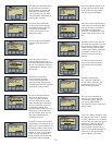
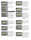
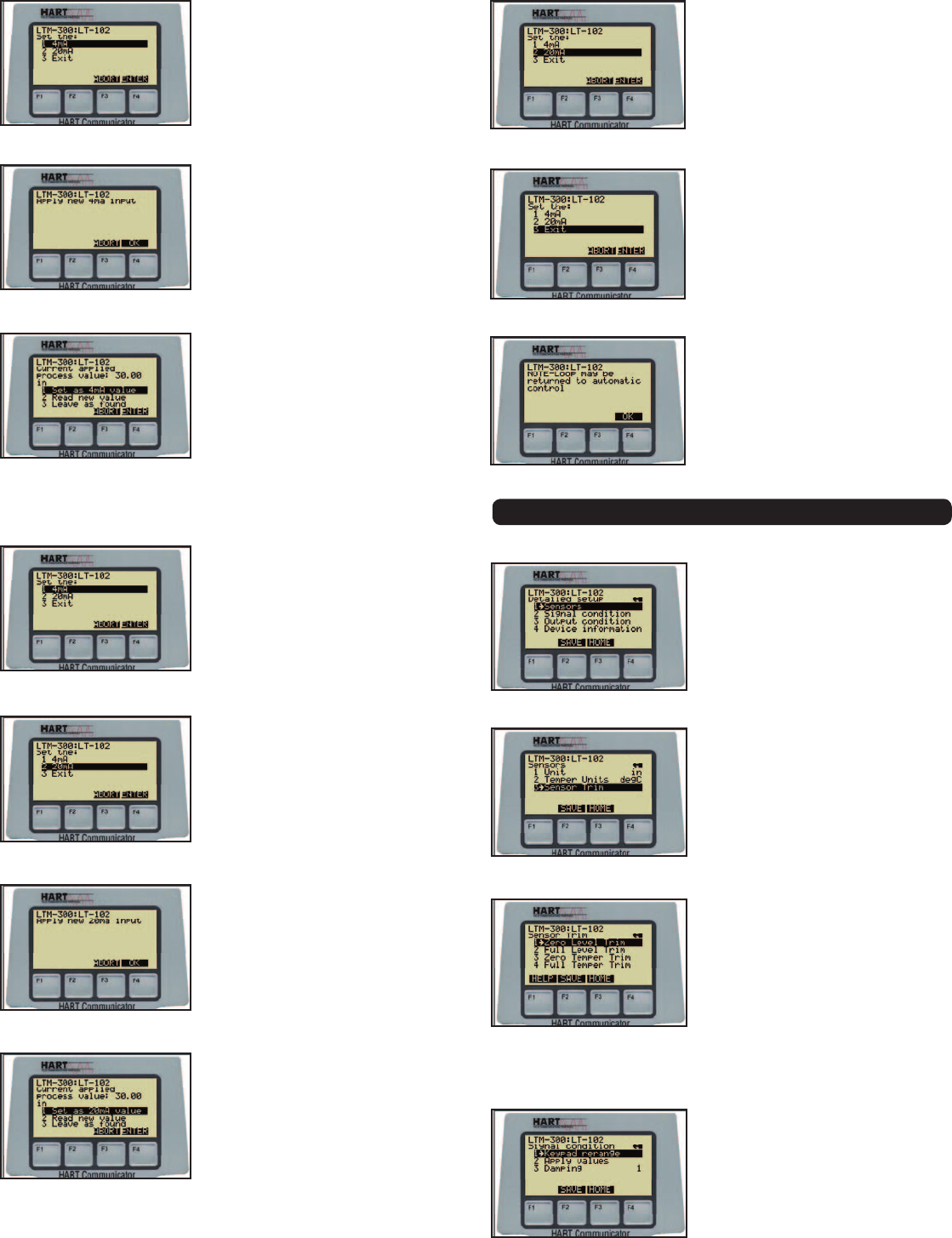
If the user desires to change the
20mA measurement value, he
selects the 20mA menu option and
must press ENTER to continue the
procedure.
The HART Communicator requests
the user to set the Level (or
Interface) to the position that is
to provide the 20mA loop current
output. When that has been done,
the user must press OK to continue
with the procedure.
The HART Communicator then
requests a measurement reading
from the transmitter indicating the
digital value at this range position.
The user then has the option of
setting this value as the upper
range value, getting an update
of the digital reading from the
transmitter or leaving the 20mA
range point as it was.
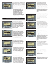
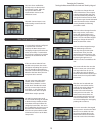
If the user accepts the
measurement value as the
20mA loop current point, the
HART Communicator issues the
command changing the URV
and when the transmitter replies,
returns to the Set screen
When the user desires to leave the
Apply values procedure, he must
select the Exit menu entry.
The user is then notified that
the loop may now be returned
to automatic control. After the
user presses OK the HART
Communicator returns to the
Rerange screen.
Detailed Setup Selections
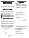
In the Overview section, it was
shown that if the user selects the
Detailed setup menu from the
Device setup screen, the following
screen presents the following
selection of menus to the user.
If the user selects Sensors from the
Detailed setup screen, he may edit
the Unit code for Level/Interface or
edit the units code for Temperature.
The third option is a menu Sensor
Trim that gives the user additional
selections.
If the user selects Sensor Trim
from the Sensors menu, calibration
procedure options are presented. If
the transmitter is not configured for
Temperature, the Zero Temper Trim
and Full Temper Trim options will
not be presented. The description
of these procedures is given in the
previous section on Calibration.
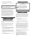
If the user selects Signal Condition
from the Detailed setup screen, he
is presented with three additional
selections. The Keypad rerange
and Apply values procedures are
presented in the Rerange section.
The third option allows the user to
modify the Level/Interface damping
factor.
17