


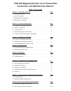


The LTM-300 is an assembly of two major components:
• The Sensor Tube Assembly. This a 5/8” diameter stainless steel probe,
sealed on one end, with the magnetostrictive waveguide in its center.
In addition to the magnetostrictive waveguide, the tube also houses
the optional temperature sensor and the detector electronics. The
tube is made to lengths of 2-30 ft. in rigid construction.
• The Electronics Housing. The extruded aluminum housing has two
separate compartments. One side contains the microprocessor board
assembly and calibration push buttons. The other side contains the
wiring termination board. The electronics module is connected to
the detector board of the sensor tube assembly via a plug-in cable.
The main board is surface mounted component construction utilizing
the latest in integrated circuit technology. It contains a high-speed
micro controller with a HART modem, D/A Converters, A/D Converter
(for optional temperature) and all other accessory components.
The LTM-300 Level Transmitter is based on the principle of
magnetostriction first used for digital delay lines and later for
precision distance or displacement in the machine tool industry. The
principle, if designed and applied properly, has potentially very high
measurement resolution, typically better than 0.001 inch. In the
machine tool industry such a high resolution is desirable. In the liquid
level measurement application, however, a resolution of 0.01 inch is
more that adequate.
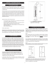
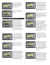
In a brief description, the magnetostrictive principle consists of a
wire extruded and heat treated under carefully chosen conditions
to retain desired magnetic properties, which is pulsed by a circuit
with a relatively high current pulse. The high current pulse produces
a circular magnetic field as it travels down the wire at the speed of
light. Another magnetic field generated by a permanent magnet,
placed near or around the wire at some distance from the point of
entry of this pulse, interferes with the magnetic field of the pulse
and torsional force results at the collision point.
SECTION 2. Instrument Description
2.0 Transmitter Detailed Description
2.1 Theory of Operation
The effect of this torsion force is to twist the wire at this point
producing a torsion wave traveling towards both ends of the wire.
The propagation time of this wave is measured precisely and, if the
wire properties remain stable, it is very repeatable at about 5-10
microseconds per inch, which is approximately the speed of sound
in that medium. By measuring the exact number of microseconds it
took the torsion wave to reach a designated termination point of the
wire, the distance to the magnet from this termination point can be
easily calculated.
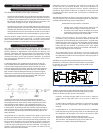
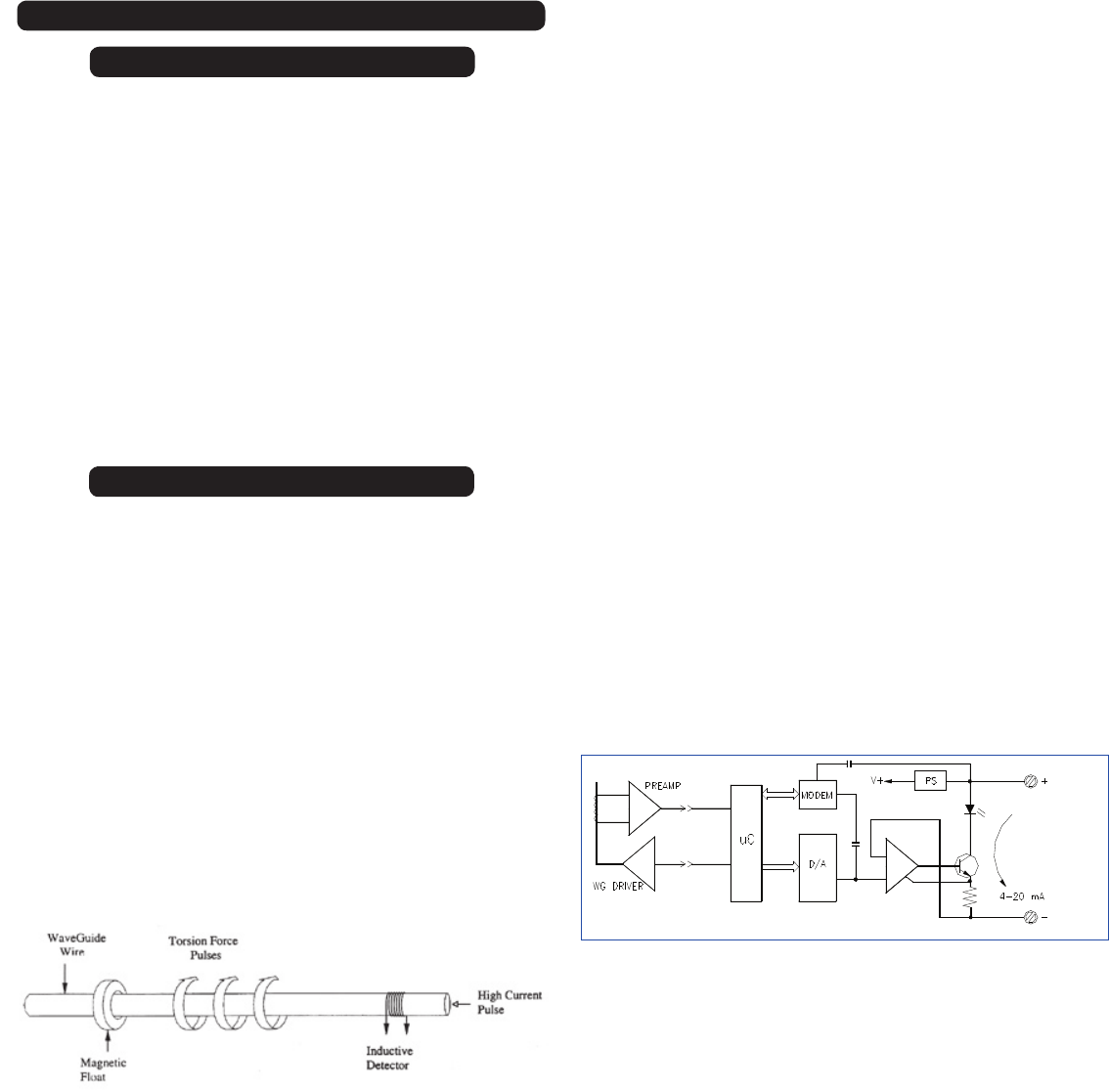
A high-speed micro controller is utilized in the design to process and
calculate the elapsed time measurement. Accurate crystals are used
for the time base to resolve sub-microsecond timing increments. The
binary number, equivalent to the microseconds of the echo travel time,
is written to an output D/A Converter and subsequently converted to
a 4-20 mA signal proportional to the item measured. The larger the
number of microseconds there are, the greater the distance of the
float from the head of the transmitter.
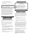
Basic Level Transmitter Simplified Block Diagram
Facilities are provided to field calibrate the range of the 4-20 mA
output using the actual position of the float and pressing a push-
button on the front panel to set the 4-20 mA point.
2
Calibration routines are included in the software to scale the 4 and
20 mA points for any distance desired. Even reverse calibration is
a simple task using the software routines. Reverse calibration is
desirable if ullage instead of full level is required, or when the probe
is installed with bottom mount head. See Section on Calibration for
further details.
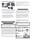
The LTM-300 transmitter can have as many as three outputs. The first is a
4-20 mA output, the second and third are digital outputs. The LTM-300 is
available with the following output configurations:
All LTM-300 Units have HART as a standard.
1. Primary Level. Single output version with only one
variable that will output a 4-20mA signal for level.
2. The second and third outputs are digital and can be
configured to measure temperature and/or interface
level. The digital outputs are read via HART.
1. Primary Level Transmitter. The most basic version of this
transmitter, is that it computes the distance between the float and
the detector from the elapsed time measurement. A specific time
window becomes active only for a short time after the interrogation
pulse is applied to the waveguide. Any feedback signal, received
before and after this window, is rejected as noise. Even signals
received during the active window are evaluated and filtered so
that only high integrity data is accepted.
The conditioned signal is converted to a percent of full-scale
number and written to the D/A Converter. The scale is defined by
the calibration procedure and it corresponds to the output span (4-
20mA) of 16.00 mA.
A deadband, corresponding to approximately six inches next to
the detector, is fixed in the software and the float is not permitted
to enter this area. If this happens, readings may be erratic or the
output may go to FAIL.
Provision, accessed through HART or front panal, is made for
a FAIL mode to High (20.8 mA), Low (3.75 mA) or “Hold last
Value.”
A HART modem enables the transmitter to communicate serially
over the 4-20 mA DC signal with a host computer or a handheld
terminal.
2. Level/Temperature. An optional temperature sensor is embedded
inside the bottom tip of the probe, and it can be calibrated to give
the temperature of the liquid in the tank on the second or third
The sensor is a 1000 ohm platinum RTD type and its
resistance is converted to a binary signal by a high resolution
A/D Converter. The temperature range is set to order and
stored in non-volatile memory before shipment.