


6.4 Start-Up for Gage-Mounted
LTM Transmitters
If the transmitter does not appear to calibrate properly, or has an erratic
output, check the deadband of the sensor tube and ensure that the
float is within the active region of the probe. The active region of the
sensor tube is typically marked with 20mA and 4mA stickers when
the unit is calibrated before shipment.
If the output is still erratic, try disconnecting the power momentarily
by unplugging and re-plugging-in the terminals. If a glitch was stored
in RAM memory, this will generally clear it.
It is possible for the LTM-300 to be magnetically biased or have
residual magnetic energy stored along the length of the waveguide.
These magnetic anomalies can interfere with the signal-to-noise ratio
and the stability of the output signal itself.
If this appears to be the case, a gage float magnet (or any magnet
available) may be run along the length of the sensor tube, past the
head of the transmitter, in an even motion and without stopping. This
will usually clear all such magnetic anomalies.
The LTM-300 is designed to operate with a supply voltage of 15-36 vdc
(at 20 mA) across its terminals without affecting the mA signal. The most
common loop supply used is 24vdc.
It is found sometimes that additional resistance in the loop is necessary,
either in the form of a second load resistor or higher resistance safety
barrier. This will appear to limit the maximum output of the transmitter
to below 20 mA. The transmitter will generally perform correctly up to
this point. To resolve this problem, the voltage of the loop supply must be
increased somewhat. Even a slight increase by one volt may be sufficient
and many supplies have such an adjustment.
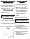
All connections must be checked for improper wiring or polarity before
power is applied. The LTM-300 has series diodes preventing the
reverse polarity from entering and damaging the circuitry. If power is
applied and the signal is 0.0 mA, chances are good that the polarity
is reversed.
SECTION 6. Troubleshooting and Maintenance
6.0 Diagnostics are Via HART
6.1 Calibration Problems
6.2 Magnetic Interface
6.3 Troubleshooting Power Supply Problems
Never move a magnet in a perpendicular motion from along
the sensor tube. This will always leave a residual field in the
waveguide which will cause the transmitter to give an erratic
output
Gage and Transmitter Installation
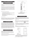
1. Visually inspect Mag-Gage and transmitter installation to
insure transmitter is positioned with the 4 mA and 20 mA
labels directly adjacent to the process connections. Make sure
transmitter is securely clamped and parallel to gage chamber.
2. Remove bottom flange and install float. Each float is clearly
tagged with serial number of the Mag-Gage and process
parameters. Top of float is clearly marked “TOP” to insure float
is in right side up.
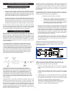
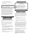
3. Inspect bottom flange for proper gasket and spring. This
spring protects float and keeps it from dropping below the
bottom process connection. To determine proper spring length
measure “A” dimension of gage. This is the length from the
center of the bottom process connection to face of the bottom
drain flange. Length of spring should be
(“A” DIMENSION) (-) Minus (Float Length + 2 inches)
EXAMPLE: “A” Dimension is 14”, Float length is 12”, + 2” = 4”
Spring Length.
14 – 12 + 2 = 4” spring
4. Float is properly installed if the bottom 2-3 flippers on gage
indicator have flipped.
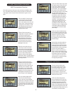
Transmitter Check-out and Calibration
NOTE: The LTM Series Transmitters are 24VDC Loop powered (2-
wire) and require a minimum of 15 Volts at 20 mA.
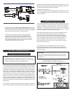
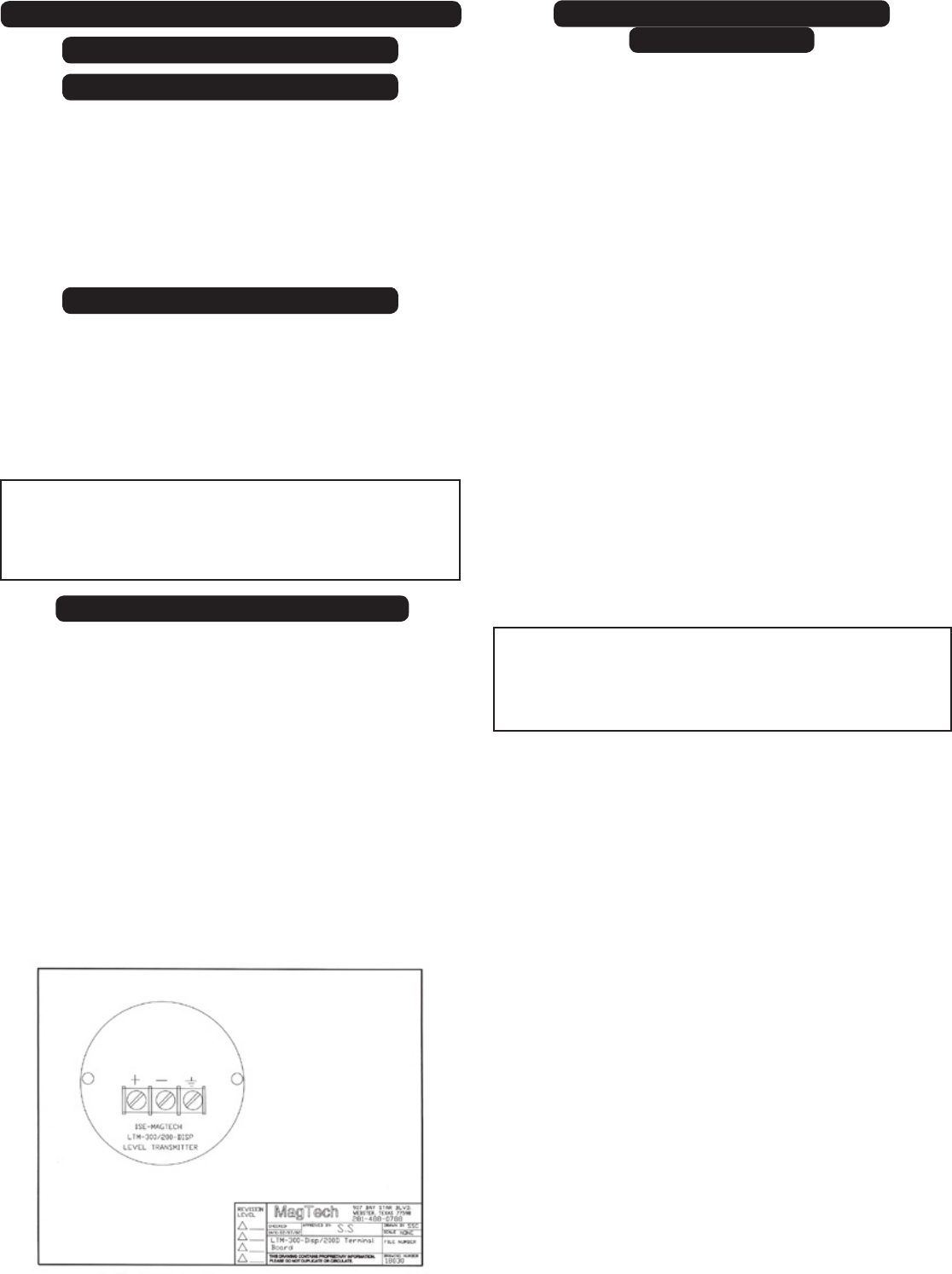
1. Using a HART compatible loop calibrator, connect the “+” terminal
on the LTM to positive lead of calibrator and the “-” terminal on the
LTM to negative lead of calibrator.
2. With float in the gage at 4mA, the output of the LTM should be
4mA. Connect the HART Communicator to the transmitter.
Upon power up, the HART Communicator should read the LRV
(lower range value) or 0 inches at 4mA.
NOTE: There is a top spring in the Mag-Gage to
protect float and prevent it from passing the top
process connection. DO NOT REMOVE EITHER
SPRING.
3. With float in the gage at 20mA, the output of the LTM should be
20mA. HART should also display URV (upper range value) or
span length in inches at 20mA.
4. To insure complete functionality of gage and transmitter, fill
the gage chamber with liquid and drain slowly to observe
transmitter and gage are tracking properly.
6
CAUTION:
TERMINAL BOARD