


Level/Interface. A second float may be added below the first one,
and the second output will be calibrated automatically. The second
time interval is measured in the same manner as the first and added
to the first to derive the position of the heavier float.
The same six inch dead zone applies to the measurement
of the second level although the reasons are different. This
will typically correspond to a physical separation of the two
floats by approximately three inches. The float size, geometry,
magnetic strength all play a factor in how close the two floats
can get without interfering with each other.
The LTM-300 can be mounted to the side of a MagTech LG series level gage
using a special mounting bracket and stainless steel hose clamps. When
mounting the transmitter to an LG series gage the active sensor region
of the probe should fall within the centerline of the process connections
on the gage. If the transmitter deadband region is inside the centerline
of the process connections the transmitter will not output an accurate
measurement because the active region of the probe is too short. When
placing an order for a transmitter to accompany an existing gage it is
important to indicate the style of the gage, the temperature and the
center-to-center dimensions. Calibration of the probe will be factory
set along the active region of the probe; however, a field calibration may
have to be performed to match the probe to the desired control room
specifications.
If a transmitter is being purchased for an interface gage, the calibration
for the probe should be done in the field to ensure a proper control room
reading. For long transmitters it may be desirable for the operator to have
the electronics housing mounted at the bottom of the gage for easy access.
THIS MUST BE SPECIFIED AT TIME OF PURCHASE.
Installation Note (European):
The cable entry devices and blanking elements of unused apertures shall
be of a certified flameproof type, suitable for the conditions of use and
correctly installed.
The LTM-300 stand-alone transmitter comes equipped with a 3/4”
compression fitting, mounted approximately 6.00” below the electronics
housing. The fitting is placed in this area to ensure the transmitter is
calibrated in the sensor tubes active region. Refer to the stand-alone
drawings for a visual description of the transmitter features. Optional
mounting configurations are available upon request.
The magnetic float used in the stand-alone unit is designed to travel
up the sensor tube with the change in fluid level. If build-up of
process or contaminates should restrict the movement of the float,
the transmitter sensor tube will have to be cleaned or the float may
have to be replaced with one that has a wider inside diameter. The
floats are designed to match the pressure and specific gravity for
the process being measured and come in various materials ranging
from stainless steel to kynar.
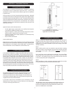
SECTION 3. Installation and Wiring
3.0 Strap-On Transmitter Installation
CAUTION:
During installation, do not attempt to twist or turn the head of the
transmitter. Damage to the detector assembly may occur if the head
is rotated . If the head is loose, please notify the factory.
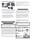
3.1 Standalone Transmitter Installation
The magnetic float can be changed out at any time to accommo-
date the processes being measured. The float stop, located at the
bottom of the transmitter, can be removed to allow the float to slide
off the sensor tube.
3
PLEASE NOTE:
If using a transmitter configured for dual level output or interface
measurements, remember to slide the float with the lightest grav
-
ity range first.
3.
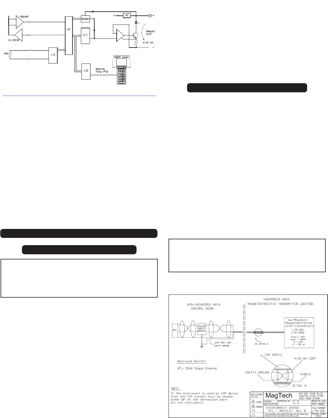
INTERCONNECT WIRING (CSA & FM)