


Ambient Temp. Range -20°C ... +40°C (-4°F ... 104°F)
Humidity Limits: SAMA PMC 31.1-5.2
Vibration Limits: SAMA PMC 31.1-5.3
RFI Limits: SAMA PMC 31.1-20 to 1000
MHz up to 30V/m
Material: 316ss standard, optional
Hastalloy, Monel, Kynar coated
Operating Temperature: -50 to 302°F (-50 to 150°C)
Maximum Pressure: 2000 psig @ 300°F
Range: 12” to 30 ft.
Supply Voltage: 15 to 36 VDC
Repeatability: .005% of full scale or .010”,
whichever is greater
Non-Linearity: .01% of full scale or .030”,
whichever is greater
Level Sensor Accuracy: .01% of full scale or .020”,
whichever is greater
Analog Output Resolution: .025% of full scale, (1) 4/20 mA
primary level.
Output: One 4-20 mA output:
Level Option: Two Digital
Outputs: Temperature and/or
Interface via HART only.
Calibration: Zero and span field adjustable
with push buttons or HART.
Secondary level is auto-
connect. Temperature is
configured via HART or AMS
only.
Diagnostics: On board diagnostics for
troubleshooting via HART or
AMS
Dampening: 1 to 25 seconds (field
adjustable) via HART
Oper. Temp. (electronics) -58 to 185°F (-50 to 85°C)
Housing: Explosion Proof, Dual
Compartment,
H” NPT, Epoxy
Coated Aluminum
Polarity Protection: Diode in series with the loop
Hazardous Location Approvals: FM - Exp Cl l , Div. I Grp. B C D,
Cl II Grp. E F G, Cl III
CSA - Ex ia (Intrinsically Safe): Cl I, Div. I, Grp. C D
Exp (Expl. Proof): Cl I, Div. I, Grp. B C D, Cl II, Grp. E F G, Cl III
IECEx (Expl. Proof): Ex d IIC T4
Atex (Expl. Proof): EEx d IIC T4 Ex II 2 G
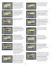
The LTM-300 transmitter is available in three different configurations. A
single output version with only one variable that will output a 4-20 mA
signal for level. The second configuration is a transmitter fitted with a
second float to provide a digital output for interface level in addition to
the primary level output. The third configuration is one 4-20 mA signal
for Primary level and two additional digital signals with one for interface
level and one for temperature output.
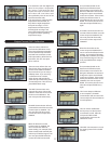
Configurations two and three have independent calibration as well
as independent outputs. These configurations have the capability for
calibration and measurement using a HART protocol communications
system. The HART specifications and conditions will be discussed in detail
under the HART COMMUNICATION section of the manual. The temperature
range is factory set from –50°F to 300°F.
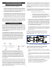
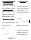
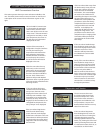
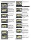
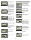
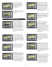
Pushbutton Calibration
Step 1 - Move jumper to the write enable position (see below)
Step 2 - Move your float or magnet to the 4mA (0%) point on the probe
Step 3 - Press the ENTER button on the display until “Trm Snsr” is
displayed. Press the UP arrow to display “Yes” and press ENTER.
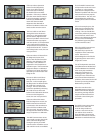
Step 4 - The display will read “Trim Zero”. Press ENTER.
Step 5 - Move the float or magnet to the 20mA (100%) point on the
probe.
Step 6 - The display will read “Trim Span” with a value above. Using the
arrow buttons, input the correct distance from the zero point and press
Enter. Calibration is now completed.
Note: “Sel Lngth” value is factory set and should not be changed. Doing
so will cause a level error indication.
SECTION 5.0 Calibration
SECTION 4. Specifications
5.0 LTM-300 Output Configurations
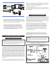
3.2 Recommended Wiring,
Single Loop
4
4.0 Transmitter Electrical Specifications
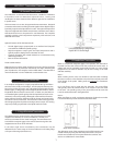
4.1 Transmitter Sensor Tube
FRONT PANEL