


9
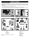
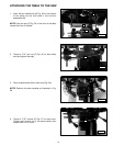
24. Table Handle (2)
25. Male Hinge (2)
26. Door Latch
27. Female Hinge (2)
28. Cord Bushing
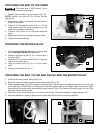
15
16
17
18
19
20
21
22
23
24
25
26
27
28
15. 5/16-18 x 1-1/2" Hex Head Screw (4)
16. 5/16-18 x 3/4" Carriage Head Bolt (16)
17. #10-24 x 1/2" Socket Head Cap Screw (8)
18. #10-32 x 1/2" Pan Head Screw (4)
19. 5/16" Flat Washer (4)
20. 7/16" Jam Nut (2)
21. 7/16" Locknut (2)
22. 5/16-18 Hex Nut (20)
23. #10-32 Hex Nut (4)
ASSEMBLY
ASSEMBLY TOOLS REQUIRED
ASSEMBLY TIME ESTIMATE
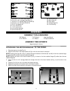
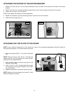
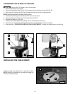
ATTACHING THE MOTOR BRACKET TO THE STAND
1. Place the stand on its side (Fig. 3).
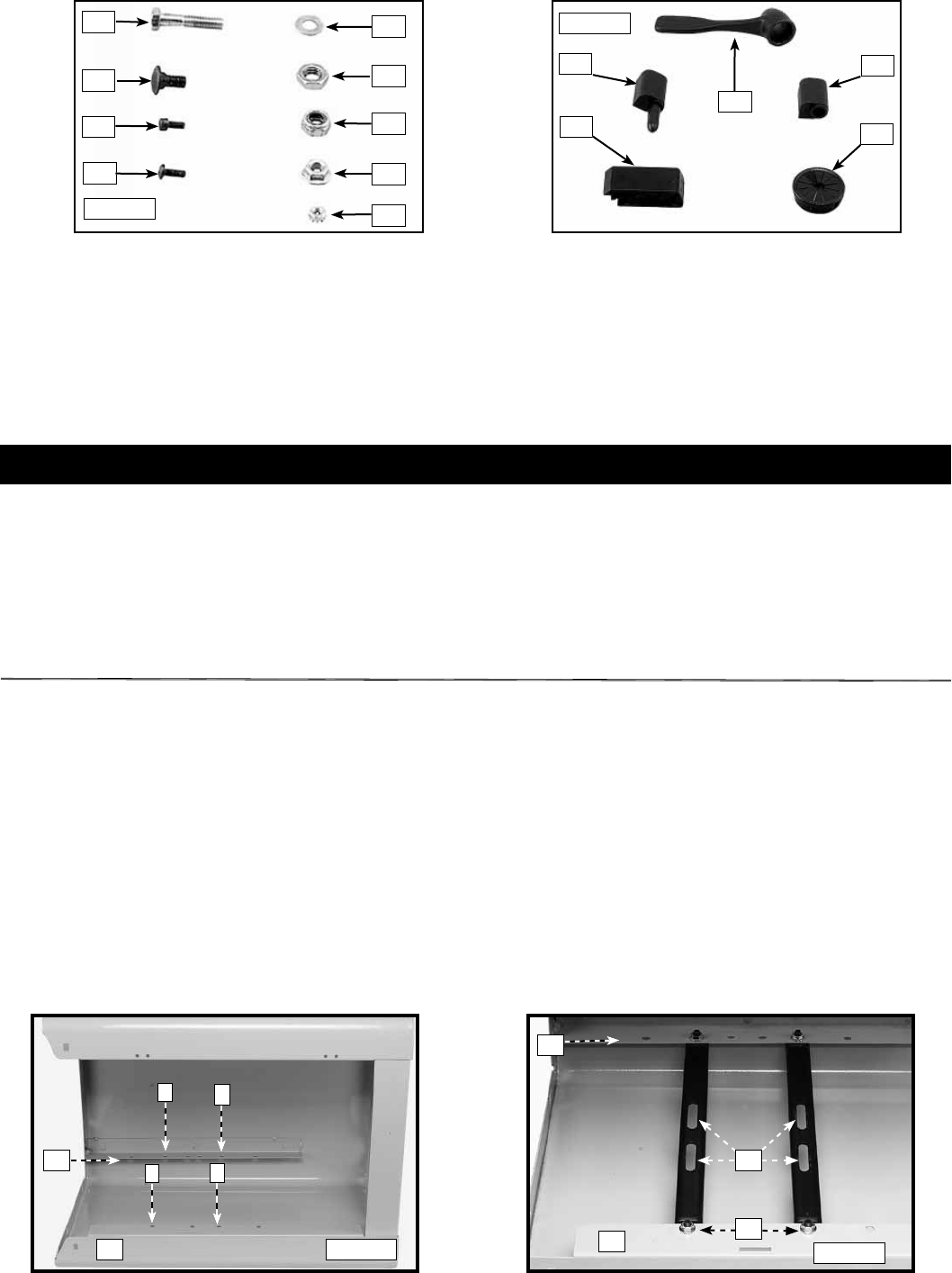
2. Align the two holes in the motor bracket (A) Fig. 4 with the two holes in the stand.
NOTE: Counting from the left of Fig. 3, attach the motor brackets to the holes (#1 and #3) in the front cabinet flange
(D), and holes (#2 and #5) in the rear cabinet flange (E).
NOTE: Position the slots of the motor bracket (C) Fig. 4 closer to the front cabinet flange (D) rather than the rear
cabinet flange (E).
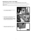
3. Insert a 5/16-18 x 3/4" carriage head bolt through the hole in the motor bracket (A) Fig. 4, and the hole in the
stand.
4. Thread a 5/16-18 hex nut on the bolt and tighten securely.
5. Repeat this process for the other hole in the motor bracket.
6. Attach the other motor bracket to the stand in the same manner.
D
E
1
3
2
5
E
D
A
Fig. 3
Fig. 4
3/8" Wrench
5/16" Wrench
7/16" Wrench
1/2" Wrench
4mm Hex Wrench
Phillips Screwdriver
Approximately 2-4 hours
C
Fig. E
Fig. F