


Model 187 & 189
Users Manual
3-6
MIN MAXHOLD
REL
%
ms
Hz
RANGE
dB
dB
ac+dc
ac+dc
ac+dc
ac+dc
F
nS
mA
mA
A
mV
V
mV
V
OFF
C
A
A
A
A
mA
COM
V
TEMPERATURE
A
MIN MAXHOLD
REL
%
ms
Hz
RANGE
dB
dB
ac+dc
ac+dc
ac+dc
ac+dc
F
nS
mA
mA
A
mV
V
mV
V
OFF
C
A
A
A
A
mA
COM
V
TEMPERATURE
A
AutoHOLD
LOGGING
SAVECANCEL
FAST MN MX
SETUP
YES
NO
1000V
400mA
FUSED
10A MAX
FUSED
CAT
CLEAR MEM
VIEW
+
ac+dc
V
ac+dc
V
LOGGING MULTIMETER
189
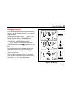
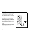
ach002f.eps
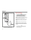
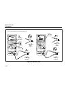
Figure 3-4. DC Voltage Measurement
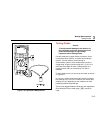
Measuring Resistance
Caution
To avoid possible damage to the meter or to
the equipment under test, disconnect circuit
power and discharge all high-voltage
capacitors before measuring resistance.
Resistance is an opposition to current flow. The unit of
resistance is the ohm (Ω). The meter measures resistance
by sending a small current through the circuit.
The meter’s resistance ranges are 500.00 Ω, 5.0000 kΩ,
50.000 kΩ, 500.00 kΩ, 5.0000 MΩ, 30.000 MΩ, and
500.0 MΩ.
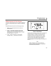
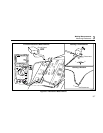
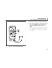
To measure resistance, set up the meter as shown in
Figure 3-5.
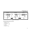
All pushbutton functions are available with resistance
measurements. The blue key cycles to continuity and
conductance measurement, which are described later in
this chapter.
Note
In the Ohms Mode, a negative sign (-) on the
display indicates the presence of voltage. This
will cause reading errors.