


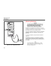

Making Measurements
Testing Diodes
3
3-13
MIN MAXHOLD
REL
%
ms
Hz
RANGE
dB
dB
ac+dc
ac+dc
ac+dc
ac+dc
F
nS
mA
mA
A
mV
V
mV
V
OFF
C
A
A
A
A
mA
COM
V
TEMPERATURE
A
MIN MAXHOLD
REL
%
ms
Hz
RANGE
dB
dB
ac+dc
ac+dc
ac+dc
ac+dc
F
nS
mA
mA
A
mV
V
mV
V
OFF
C
A
A
A
A
mA
COM
V
TEMPERATURE
A
AutoHOLD
LOGGING
SAVECANCEL
FAST MN MX
SETUP
YES
NO
1000V
400mA
FUSED
10A MAX
FUSED
CAT
CLEAR MEM
VIEW
+
+
+
+
+
+
+
+
+
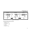
LOGGING MULTIMETER
189
ach005f.eps
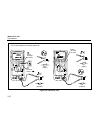
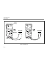
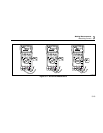
Figure 3-8. Capacitance Measurement
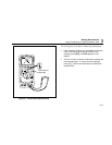
Testing Diodes
Caution
To avoid possible damage to the meter or to
the equipment under test, disconnect circuit
power and discharge all high-voltage
capacitors before testing diodes.
Use the diode test to check diodes, transistors, silicon
controlled rectifiers (SCRs), and other semiconductor
devices. The test sends a current through a
semiconductor junction, then measures the junction’s
voltage drop. A typical junction drops 0.5 V to 0.8 V. In
diode test, the beeper is active. It beeps briefly for a
normal junction and is on continuously if a short is
detected.
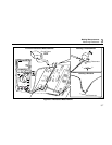
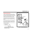
To test a diode out of a circuit, set up the meter as shown
in Figure 3-9.
In a circuit, a similar diode should still indicate a forward-
bias reading of 0.5 V to 0.8 V; however, the reverse-bias
reading can vary depending on the resistance of other
pathways between the probe tips.
The blue key toggles between diode test and capacitance.
Since diode test uses a fixed range, R cannot be
used.