


Model 187 & 189
Users Manual
3-8
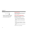
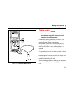
Keep the following in mind when measuring resistance:
• Because the meter’s test current flows through all
possible paths between the probe tips, the measured
value of a resistor in a circuit is often different from
the resistor’s rated value.
• The test leads can add 0.1 Ω to 0.2 Ω of error to
resistance measurements. To test the leads, touch
the probe tips together and read the resistance of the
leads. If necessary, you can press D to
automatically subtract this value.
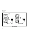
The resistance function can produce enough voltage to
forward-bias silicon diode or transistor junctions, causing
them to conduct. To avoid this, do not use the 30 MΩ or
500 MΩ ranges for in-circuit resistance measurements.
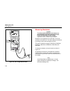
Testing for Continuity
Caution
To avoid possible damage to the meter or to
the equipment under test, disconnect circuit
power and discharge all high-voltage
capacitors before testing for continuity.
Continuity is the presence of a complete path for current
flow. The continuity test features a beeper that sounds if a
circuit is complete. The beeper allows you to perform
quick continuity tests without having to watch the display.
The continuity function detects intermittent opens and
shorts lasting as little as 1 millisecond (0.001 second).
These brief contacts cause the meter to emit a short beep.
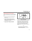
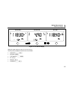
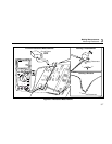
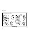
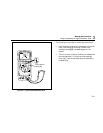
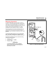
To select continuity, turn the rotary switch to resistance
position, then press the blue button once. The continuity
symbol (~) appears in the display. Continuity uses
manual ranging only; autoranging is not available. Refer to
Figure 3-6 for continuity testing setup instructions.